
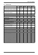
Technical data

6 720 611 445 GB (03.11)
8
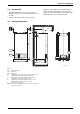
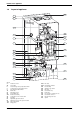
Details of the appliance
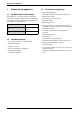
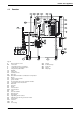
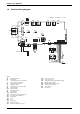
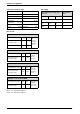
1.8 Electrical wiring diagram
Fig. 4
4.1 Ignition transformer
4.4 Y-S module
6 Temperature limiter, heat exchanger
9 Flue gas temperature limiter
32 Flame sensing electrode
33 Ignition electrode
36 Temperature sensor in boiler flow
52 Solenoid valve 1
52.1 Solenoid valve 2
56 Gas valve CE 427
61 Reset button
135 Master switch
136 Temperature control for boiler flow
151 Fuse, slow 2.5 A, AC 230 V
153 Transformer
161 Link
226 Fan
300 Code plug
302 Earth connection
310 Function control (Service only)
312 Fuse, slow T 1,6 A
313 Fuse, slow T 0,5 A
328 Terminal block for AC 230 V Mains supply
363 Indicator lamp for burner
364 Indicator lamp for power supply
365 “Chimney sweep” button
366 Service button
367 No function
6 720 610 601-03.2O
mains supply
r
r
bl
bl
bl
bl
o
o
o - orange bl - black r - red
6
9
32
33
36
52.1
52
56
61
230 V
135
25 V
230V/AC
153
136
151
12
4
7
89
161
M
226
300
L
NLs
Ns
328
LR
302
310
312
313
363
364
365
366
ECO
367
4.1
4.4