
Technical data


6 720 611 445 GB (03.11)
22
Electrical connections
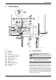
4.2 Wiring to your system
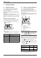
Mains electricity supply: The boiler should be con-
nected to the permanent mains supply as described in
section 4.1 This also provides the electrical supply to
the system.
Note: This must be the only electrical supply to
the system. This ensures the safety of a single
fused supply.
The boiler can only be wired to a remote system junction
box.
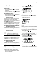
Note: A pump is not built into the boiler and must be fit-
ted externally.
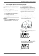
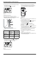
The diagram shows the overall wiring details. A cable is
fitted at the factory, between the boiler control panel
and the Y-S module. This module is designed to provide
the correct voltage interface.
The other connector in the module must be used for wir-
ing to the remote junction box as shown. It is the
responsibility of the installer to connect all other system
components i.e. water valve/s, pump, programmer etc.
to the proprietary junction box according to the instruc-
tions supplied with the box. Worcester Heat Systems
cannot be held responsible for any incorrect wiring to
these parts of the system.
If a room thermostat and/or frost thermostat is required,
these must also be connected to the junction box
according to the proprietary instructions.
Upon completion of the electrical connections check for
earth continuity, correct polarisation and resistance to
earth.
Note:
Fig. 30 Wiring to the Y-S module
Table 10
Y-S Module Remote Junction Box
LS L
NS N
PE E (Earth)
DV Demand (Switched Live)
L
NN
S
L
S
L
R
Timer
Tank Stat
Room Stat
Frost Stat
System
Water
Valve(s)
Terminal
Strip
This must be the only electrical
supply to the Junction Box
OUTSIDE
OF BOILER
INSIDE
OF BOILER
CONTROL
BOARD
HEATRONIC CONNECTOR
PRE-WIRED
INSTALLATION
WIRING
REMOTE PRE-WIRED
˜ JUNCTION BOX
Other connections to
Terminal Strip according
to Proprietary instructions
Y-S-Module
MAINS 230V
LIVE SUPPLY
TO BOILER AND
SYSTEM
PUMP
LR
LS
NS
PE
PE
DV
LS
NS
E
N
L
BOILER/PUMP
˜DEMAND
MAINS SUPPLY