
Technical data

18
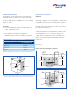
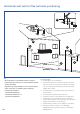
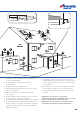
Horizontal and vertical flue terminal positioning
16
600
300
200
300
1,200
Boundary Line
1,500
1,500
2
1
12
11
10
9
5
18
7
6
13
15
4
3
17
14
300
300
300
300
300
300
300
500
600
300
600
600
400
300
25
8
300
500
600
300
25
2
25
16
2m
1m
52mm
104mm
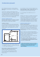
Note
•
All measurements are the minimum clearances required
•
Terminals must be positioned so to avoid combustion products
entering the building
•
Support the flue at approximately one metre intervals and at a
change of direction, use suitable brackets and fittings.
Flue bracket part numbers:
7 716 191 092 (100mm dia.)
7 716 191 173 (100mm dia. x 6)
7 716 191 174 (125mm dia.)
Key to illustration
1. 300mm adjacent to a boundary line.
2. The dimension below eaves, balconies and car ports can be
reduced to 25mm, as long as the flue terminal is extended to
clear any overhang. External flue joints must be sealed with
suitable silicon sealant.
3. 1,500mm between a vertical flue terminal and a window or
dormer window.
4. 1,200mm between terminals facing each other.
5. Vertical flue clearance, 300mm adjacent to a boundary line.
6. 600mm distance to a boundary line, unless it will cause a
nuisance. BS 5440:Part 1 recommends that care is taken when
siting terminal in relation to boundary lines.
7. 600mm minimum clearance from a skylight to a vertical flue.
8. Vertical flue clearance, 500mm to non-combustible
building material, and 1,500mm clearance to combustible
building material.
All measurements in millimetres