
Technical data


SERVICING AND SPARES
6 720 648 547 (2012/06) 41
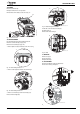
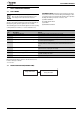
11. PCB REMOVAL
To gain access to the PCB:
▶ Remove the five screws shown in the diagram below and remove the
PCB cover.
Fig. 64 PCB access
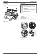
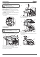
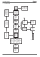
12. FAN ASSEMBLY
▶ Remove electrical connector from fan.
▶ Remove condensate trap (see page 36).
1. Undo the union connection (A) from the top of the gas valve.
▶ Remove wire clip (B) from air/gas adjustment assembly (C) then pull
gas pipe down.
2. Unscrew two screws (D).
3. Remove fan from boiler.
4. Remove three screws retaining the air/gas adjustment assembly (E).
▶ Reassemble with new fan assuring that seals are correctly fitted.
Fig. 65 Fan assembly removal
6720647361-36.2Wo
NOTICE: Air/Gas ratio
▶ After re-assembly the combustion must be checked
using the procedure in the section “Setting the air/gas
ratio.”
▶ The setting of the gas ratio must be carried out by a
competent person.
Setting the air/gas ratio must not be attempted unless
the person carrying out the operation is equipped
with a combustion analyser conforming to BS 7927
and is competent in its use.
B
C
A
D
2.
1.
6720647361-37.2Wo
E
8.
3.
4.