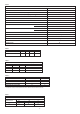
35CDi WALL MOUNTED COMBINATION BOILER FOR CENTRAL HEATING AND MAINS FED DOMESTIC HOT WATER INSTALLATION AND SERVICING INSTRUCTIONS 35CDi This appliance is for use with Natural Gas or LPG (Cat II 2H3P). GC NUMBER 47 311 39 (N.G.) GC NUMBER 47 311 40 (L.P.G.) CE 97/0086 APPLIANCE OUTPUTS Minimum Maximum Natural Gas Domestic Central Hot Water Heating 9.0 kW 9.0 kW 35.17 kW 25.0 kW LPG (Propane) Domestic Central Hot Water Heating 12.9 kW 12.9 kW 35.17 kW 25.
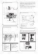
Contents 1. 2. 3. 4. 5. 6. 7. 8. 9. Installation Regulations .............................................. Page Introduction.................................................................. Page Technical Data .............................................................. Page Siting the Appliance .................................................... Page Flue Terminal Position ................................................ Page Air Supply ................................................................
2.5 Flue 2.5.1. The flue can be to the right, left or rear. 2.5.2. The flue terminal, on the outside wall, must not be obstructed or damaged. 2.5.3. A terminal guard, Type K2 - GC 393 553, is available from Tower Flue Components, Vale Rise, Tonbridge TN9 1TB 2.5.4. An internal flue fitting kit is available. Fitting instructions are given in Section 11.9. 2. 6. Controls 2.6.1. Control knob for switching the appliance On or Off. 2.6.2. Control knobs for adjusting the CH or DHW temperatures. 2.6.3.
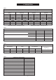
3. Technical Data Table 1. kW 9.0 25.0 35.17 Btu/h 30,700 85,300 120,000 NOMINAL BOILER RATINGS (10 Minutes After Lighting) BOILER ADJUSTED FOR G20 (Natural Gas) BURNER SETTING INPUT (Net) PRESSURE kW Btu/h m bar. in. wg. 11.42 38,900 1.5 0.6 28.52 97,300 8.3 3.3 39.61 135,100 14.2 5.8 12.9 25.0 35.17 44,000 85,300 120,000 16.5 29.14 40.5 OUTPUT GAS RATE 3 m /h 1.19 2.97 4.12 ft3/h 41.98 104.8 145.5 BOILER ADJUSTED FOR G31 (Propane) 56,300 6.0 99,400 19.0 138,200 34.7 0.68 1.23 1.64 24.0 43.
Table 5 PERFORMANCE SPECIFICATIONS PRIMARY WATER CAPACITY 3.0 litres MAXIMUM MAINS INLET PRESSURE 10 bar MINIMUM MAINS INLET PRESSURE (working) for max. hot water flow 1.3 bar MINIMUM MAINS INLET PRESSURE (working) to operate appliance 0.8 bar MAXIMUM CENTRAL HEATING FLOW TEMPERATURE 82°C nom MAXIMUM CENTRAL HEATING SYSTEM SET PRESSURE 1.5 bar MINIMUM CENTRAL HEATING SYSTEM PRESSURE 0.
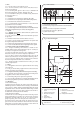
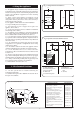
Fig. 3. Casing Dimension and Clearances 4. Siting the Appliance 35 4.1. The appliance may be installed in any room but refer to the requirements of the current IEE regulations and, in Scotland, the relevant electrical provisions of the Building Regulations with respect to the installation of appliances in rooms containing baths or showers. 4.2.
5.3. The terminal must not cause an obstruction nor the combustion products a nuisance. 5.4. Under some climatic conditions the terminal might steam. Positions where this might be a nuisance should be avoided. Combustion products must not enter the roof space. 5.5. If the terminal is within 1m of a plastic or painted gutter or within 500mm of painted eaves then an aluminium shield at least 750mm long should be fitted to the underside of the gutter or painted surface. 5.6.
. Domestic Hot Water Fig 8 - System Make Up 8.1. If necessary reference should be made to the local water company before connecting the appliance. 8.2. Devices which would prevent the flow of expansion water must not be fitted unless separate arrangements have been made. A mini-expansion vessel can be fitted within the casing if necessary. A thread sealant suitable for potable water must be used. 8.3. The last 600mm of mains water pipe before the appliance must be in copper. 8.4.
10.10. On very rare occasions an external frost thermostat might be considered where parts of the system are remote from the appliance. Refer to Worcester Heat Systems Technical Department for more information - Tel: 0990 266241. 10.11. A radio frequency room thermostat is available for use with the appliance. 10.12. Safety check: If there is an electrical fault after installation check for fuse failure, short circuits, incorrect polarity of connections, earth continuity or resistance to earth.
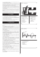
Fig 13 - Pictorial Wiring Diagram 2 Orange 2 Red 14 Black Red White 13 1. Spark Generator 12 2. 6 Way In-Line Connector 6 Wires from Bottom of Boiler Green 15 Green 3. 2 Way In-Line Connector 4. Gas Valve 5. Flow Switch 6. DHW Sensor 7 7. Spark Electrode 8 8. Sense Electrode Blue 9. CH Pump 10. DHW Pump 4 11. Pump Relay PCB Violet Grey Yellow Brown 9 6 10 w llo Ye ack Bl ck a Bl 12. CH Sensor 13. Fan 1 14.
Fig 14 - Functional Wiring Diagram CH Demand Indicator Spark Electrodes DHW Demand Indicator N Flame Detect Indicator Mains Indicator Red Red Red Green Electronics Spark Indicators Fuse F2 (1.
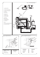
Fig 17- Front View of Appliance (control panel removed) 3 28-Fig 55 1-Fig 22 4-Fig 57 2-Fig 23 27-Fig 55 5-Fig 61 26-Fig 42 6-Fig 42 25-Fig 36 7-Fig 57 8 24-Fig 43 9-Fig 44 10-Fig 45 23-Fig 59 22-Fig 56 21-Fig 46 11-Fig 38 20-Fig 40 12-Fig 38 13-Fig 27 19-Fig 49 18-Fig 49 14-Fig 27 15-Fig 41 17-Fig 27 16-Fig 41,27 12 1. Fan & Flow Sensor 2. Fan Connections 3. Combustion Products Test Point 4. Overheat Thermostat 5. Air Pressure Switch 6. Flue Hood 7. Overheat Thermostat Phial 8.
Fig 19- Side Flue Opening Position 11. Installation 160 11.1. General. 11.1.1. The appliance is suitable for sealed systems only. 11.1.2. The flue must be installed in accordance with BS5440:1. 11.2. Unpacking and appliance preparation 11.2.1. Remove the appliance from its packing and lay it on its back. 11.2.2.
Fig 21-Casing and Control Panel Fixing Screws Fig 22- Fan and Air Flow Sensor Fixing - Negative 2. Inner Casing Fixing Screws (4) 2 5 1 4 8 + 2 +Positive 4 3 3. Control Panel Fixing Screws (2) 1. Electrical connections 2. Fan Assembly Fixing Screw 3. Fan Mounting Plate 4. Fan Casing 4. Controls Connection Fixing Screws (3) 3 1 7 - 1.Transport Bracket and Bottom Panel Fixing Screws (2) 6 5. Air Flow Sensor 6. Flue Duct Clamp 7. Air Flow Sensor Fixing Screw 8.
11.7.6. Check that the gas and water valves are closed. Refer to Fig 26. 11.7.7. Lift the appliance onto the wall mounting plate/manifold assembly ensuring that the connections fully enter the manifold fittings after it is supported at the top. 11.7.8. Secure the gas and water connections. 11.7.9. Fit a discharge pipe to the relief valve leading it away from any electrics or where it might be a hazard. The pipe must not be less than 15mm in diameter and must run continuously downward outside the appliance.
11.8.3. Mark and cut the air and flue ducts to length. Always check the dimensions before cutting. Do not cut the drilled or the expanded ends of the ducts. Make the cuts square and smooth. 11.8.4 Assemble the air and flue ducts and the terminal assembly as shown in the diagrams. Do not forget to fit the flue support to an extended duct system. Refer to Fig 31,32. 11.9. Internal fixing of the ducts 11.9.1. Fit the wall sealing collar and fix in place using the clip. Refer to Fig 33. 11.9.2.
1. Auto Air Vent 2. Cap 3. Primary (CH) Sensor Behind the Auto Air Vent 4. Flue Hood 5. Flue Hood Clamp 6. Primary Flow Manifold 7. Manifold Fixing Screw Fig 35-Auto Air Vent Fig 34-Air Duct into Clamp 2 1. Boiler Casing 5 1 2. Air Duct Clamp Assembly 1 3 2 3. Air Duct 4. Silicone Rubber Ring 3 5 4 6 4 7 5. Flue Duct 12. Commissioning 11.10.5. Refit the fan in the appropriate position ensuring that the flue duct enters the fan outlet by 20mm before tightening the clamp as shown in Fig 36.
12.6. Remove the cap from the front of each pump and turn the exposed shaft about half a turn using a flat bladed screw driver. Replace the caps. Refer to Fig 38. 12.7. Set the system pressure by filling the system until a pressure of 1.5 bar shows on the gauge and check for water soundness. Release water from the system through the pressure relief valve until the system design pressure is obtained. System pressure in bar = Static head + 0.3. Note 1bar = 10.2 metres of water.
Balance the system so that the specified temperature difference is obtained. Shut the radiators and adjust the bypass until the same temperature difference is obtained. Refer to Fig 41. Set the room thermostat to minimum and check that the burner goes out and comes back on after a period of about three minutes after the room thermostat is reset to maximum. Switch the burner off by setting the CH temperature control knob to off. 12.21. Turn off the electricity to the appliance.
Fig 42-Flue Hood Fixing Fig 45-Burner Assembly 1 2 2 1 3 4 3 8 6 4 1. Clamp Location 2. Flue Hood Clamp 7 1. Burner Blade Assembly Fixing Screw (2) 2. Burner Blade Assembly 3. Burner Location Slot 4. Burner Manifold With Injectors 3. Flue Hood 4. J-Bolt and Wing Nut 5 5. Manifold Support Bracket 6. Burner Blade Locating Screw 7. Manifold Fixing Screw 8. O-Ring Fig 43-Spark Electrode 1 2 14.4.5 Clean the primary heat exchanger. Cover the burner manifold.
Replace any components removed from the appliance in the reverse order using new gaskets/O-rings/sealant where necessary. Always check that any electrical connections are correctly made and that all screws are tight. Remove casing and cover panels and lower the facia, as necessary, to gain access to the controls. Refer to Clause 14.3.1.1-7. 15.4.1. Gas valve Disconnect or unplug the electrical connections at the valve. Remove the bottom panel.
15.4.9. Inlet Water Filter Drain the hot water circuit. Refer to 15.3.2. Remove the bottom panel. Lower the facia. Disconnect the inlet water pipe at the manifold and the flow switch. Remove the filter. Ensure that the new filter is correctly aligned. Refer to Fig 49. 15.4.10. Flow Switch Drain the hot water circuit. Refer to 15.3.2. Lower the facia. Unscrew and remove the flow switch. Ensure that the new switch is correctly aligned with the arrow pointing upwards.. Refer to Fig 49. 15.4.11.
15.4.17. CH Sensor Remove the inner casing cover. Carefully pull off the connections and release the clip to remove the sensor. Apply heat transfer paste to the face of the new sensor. Refer to Fig 55. Note: If a left-hand flue is fitted then it is easier to remove the sensor and clip before pulling off the connections 15.4.18. DHW Sensor Lower the facia. Carefully pull off the connections and unscrew the clip to remove the sensor. Apply heat transfer paste to the face of the new sensor. Refer to Fig 56.
Use new seals and gaskets where necessary. Refill and pressurise as described in Section 12.4-8 - Commissioning. Refer to Fig 59. 15.4.23. Auto Air Vent Remove the inner casing cover. Drain the primary system. Refer to 15.3.1. Unscrew and remove the auto air vent. Remove the cap from the newly fitted vent. Refill and pressurise as described in Section 12.4-8 Commissioning. Refer to Fig 35. 15.4.24. Primary Gas to Water Heat Exchanger Remove the inner casing cover. Drain the primary system. Refer to 15.3.1.
Fig 59-Domestic Hot Water Heat Exchanger Fig 60-Primary Heat Exchanger Fixing 1 1 2 1. Fixing Clip (2) 2. Domestic Hot Water Heat Exchanger 2 3 5 3. Cold Water Inlet 6 5 4. O-Ring 4 5. Domestic Hot Water Flow 4 1. Fixing Clip (2) 2. Clip Locating Channel 3. Primary Heat Exchanger 4. Clip Locating Groove 3 Fig 61-Air Flow Switch 5 5 1. Air Pressure Switch 2. Electrical Connection 3. Electrical Connection 4. Air Flow Sensing Tube Connections REAR FRONT 5. O-Ring 6.
16. Short Parts List GC Key No.
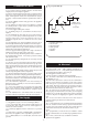
17. Operational Flow Diagrams CENTRAL HEATING FUNCTION MAIN SWITCH ON CENTRAL HEATING DEMAND CH light On. Pump On. Fan high 2 second then Low Speed. Ignition Sequence.
OVERRUN FUNCTION Within four minutes of last hot water demand AND primary temperature above 80°C If heat demand has occured in last 30 minutes Run pump until primary drops to 80°C If heat demand has NOT occured in last 30 minutes Run pump until primary drops to 80°C If primary temperature still increases above 90° C Run pump for 2 seconds AUTOFROSTSTAT FUNCTION AUTOFROSTAT FUNCTION No demand and primary temperature below 8°C Internal “Autofrostat” demand Wait in normal off state for 30 minutes R
The electronic control system for this appliance uses the four lights on the facia. These show the normal operating status and, by flashing, help to provide a fault diagnostic system. With individual or groups of lights being permanently off, on or flashing, every normal fault can be identified. 18. Fault Finding Note: This information is for guidance only. Worcester Heat Systems cannot be held responsible for costs incurred by persons not deemed to be competent. Preliminary Checks.
Is the facia on/off switch turned on? `(Clockwise) No Turn switch on. FAIL POINT A Yes Is there a 230V AC live supply across Terminal ST12 pins L and N No Check electrical supply to boiler. Yes Has fuse F1 blown? No Replace control board (Section 15.4.11) Yes Replace fuse and investigate cause. Suggestions: Cable damage, connections to (or faults within) pump, fan, external 230V controls, transformer or board.
No Yes Remove multiway connector from board position ST16. With tap still open is there continuity across contacts 19 and 20 (2 pink wires)? No Separate the 2 way in-line connector to flowswitch (fitted to boiler side panel). With tap still open, is there continuity across the two terminals still fixed to side panel? Take care not to damage terminals Replace Flow Switch No Yes Yes Red diode is damaged. Replace control board. (Section 15.4.
Is the gas supply connected and at the correct pressure? No Rectify gas supply problem. Yes Remove front panel. Reset and restart the boiler. Can a flame be seen through the spy glass? No Remove inner cover. Reset and restart the boiler. Does a spark occur across the electrodes? No Are the electrodes and gap and connections in good order? No Repair or replace electrodes (Section 15.4.2/3) or HT leads Yes Replace control board. (Section 15.4.11).
Is the multiway connector at board position ST16 pushed fully home on to the board? No Push fully home. FAIL POINT I “Sensor Fault” Yes Remove multiway connector from board position ST16. Test resistance across contacts 17 and 18 (yellow & either black wires). Is it between 1 kohm and 30 kohm? No Yes Replace control board (Section 15.4.11). No Separate 6 way in-line connector and check continuity of red wires to determine a harness fault.
Does this fault only occur in CH or DHW mode? Yes No Remove fan connector from board position ST1 and restart boiler in the fault mode. After 5 seconds is there mains 230V from the left (N) track at ST1 and right (L) track if DHW mode? Centre (L) track if CH mode? No Replace control board. (Section 15.4.11). Yes FAIL POINT J “Air or Water Pressure Fault” Repair or replace fan (Section 15.4.15) or cable. Does the fan run at all before the fault occurs? No Turn off boiler.
FAIL POINT K Light indication during fault not covered by above details. Control board is likely to be wet or damaged or malfunctioning. Check for wet board or connections. Dry and re-use or replace control board. (Section 15.4.11). Hot water temperature always too hot during a demand (not regulating). Hot water sensor could be off or poorly fixed to pipe. Repair or replace sensor. (Section 15.4.18).
This manual is to be used in conjunction with the variant part number of the bar code below: Worcester Heat Systems Limited, Cotswold Way, Warndon, Worcester WR4 9SW. Telephone: (01905) 754624. Fax: (01905) 754619. Technical Helpline (0990) 266241. This booklet is accurate at the date of printing but will be superseded and should be disregarded if specifications and/or appearances are changed in the interests of continued improvement.