24CDi/28CDi/35CDi II RSF WALL MOUNTED COMBINATION BOILER FOR CENTRAL HEATING AND MAINS FED DOMESTIC HOT WATER INSTALLATION AND SERVICING INSTRUCTIONS GC NUMBER (N.G) GC NUMBER (L.P.G.) 24CDi 47 311 30 47 311 31 28CDi 47 311 34 47 311 35 35CDi II 47 311 58 47 311 59 BOILER OUTPUT Automatic Modulating Control 24CDi 28CDi 35CDi II Domestic Hot Water 9 - 24kW 9 - 28kW 9.5 - 35.3kW Central Heating 9 - 24kW 9 - 24kW 10.5 - 27.
Contents 1. 2. 3. 4. 5. 6. 7. 8. 9. 10. Installation Regulations .............................................. Page General Information .................................................... Page Technical Data .............................................................. Page Siting the Appliance .................................................... Page Siting the Flue Terminal .............................................. Page Air Supply ..................................................................
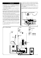
The clearances specified for servicing must be maintained. Refer to Fig. 2. 2.6 Flue The appliance has a multi-directional horizontal fanned flue system. The standard telescopic flue assembly accommodates flue lengths from 297mm to 725mm. Extension flue lengths available are from 726mm up to 4000mm (24CDi) or up to 3000mm (28CDi and 35CDi II). A vertical flue assembly kit is available. Optional 45° and 90° flue bends are available.
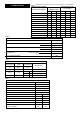
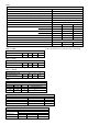
Table 1 Note: Gross Heat Input x 0.901 (NG) or x 0.922 (propane) = Net Heat Input. 3. Technical Data NOMINAL BOILER RATINGS BOILER ADJUSTED FOR BOILER ADJUSTED FOR (10 minutes after lighting) G20 (Natural Gas) G31 (Propane) 24CDi 28CDi 35CDi II kW 24.0 28.0 35.3 24.0 28.0 35.3 MAX. INPUT (net) kW 27.0 31.5 39.2 27.0 31.5 39.2 BURNER PRESSURE mbar 14.8 15.5 13.5 35.5 35.5 34.7 2.9 3.3 4.15 1.13 1.3 1.6 3 m /h MAX. OUTPUT (CH) kW 24.0 24.0 27.5 24.0 24.0 27.
Table 5 PERFORMANCE SPECIFICATIONS PRIMARY WATER CAPACITY 2.0 litres MAXIMUM MAINS INLET PRESSURE 10 bar MINIMUM MAINS INLET PRESSURE (working) for max. hot water flow 1.2 bar MINIMUM MAINS INLET PRESSURE (working) to operate appliance 0.7 bar MAXIMUM CENTRAL HEATING FLOW TEMPERATURE 82°C nom MAXIMUM CENTRAL HEATING SYSTEM SET PRESSURE 1.5 bar DOMESTIC HOT WATER TEMPERATURE RANGE 50 - 62°C 24CDi OUTPUT TO DOMESTIC HOT WATER 28CDi 35CDi II NATURAL GAS (G20) 9.0 - 24 kw 9.0 - 28kw 9.
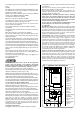
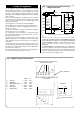
4. Siting The Appliance Fig. 2. Appliance casing dimensions and required clearances. 4.1 The appliance may be installed in any room although particular attention is drawn to the requirements of the current I.E.E. Wiring Regulations BS 7671 and, in Scotland, the electrical provisions of the Building Regulations applicable in Scotland, with respect to the installation of appliances in rooms containing baths or showers.
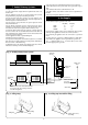
5. Siting The Flue Terminal 6. Air Supply The flue system must be installed following the requirements of BS5440:1. The standard uncut flue kit length is 425 - 725mm. Extension kits for flues up to 4m (24CDi), 3m (28CDi and 35CDi II) are available. The terminal must not cause an obstruction nor the combustion products a nuisance.
7.11 The pump is set at maximum and must not be adjusted. 7.12 Connections in the system must resist a pressure of up to 3bar. 7.13 Radiator valves must conform to BS2767:10. 7.14 Other valves used should conform to the requirements of BS1010. 7.15 No special system inhibitor is needed. 7. Sealed Primary Systems See Figs. 5, 6 and 6a 7.1 The system must comply with the requirements of BS 6798 and BS 5449. 7.
.4 A pressure relief valve is not required on an open vented system. 9.5 Air within the appliance will be expelled via the feed and vent connection or dissipated into the rest of the system which must be fitted with manual air vents at any high point. 9.6 The pump is set to maximum and must not be reset. 9.7 If it is required to use the appliance for domestic hot water before the central heating circuit is connected, a 22mm copper by-pass must be connected between the central heating flow and return.
11.9. On very rare occasions an external frost thermostat might be considered where parts of the system are remote from the appliance. Refer to Worcester Heat Systems Technical Department for more information - Tel: 08705 266241. 11.10. A radio frequency room thermostat is available for use with the appliance. 11.11. Safety Check: If there is an electrical fault after installation check for fuse failure, short circuits, incorrect polarity of connections, earth continuity or resistance to earth. 11.
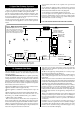
ST1 Centre Pin ST15 Pin L Electronics Electronics 2 SPEED FAN ST1 Pin L REL 4 On/Off switch REL 3 ST1 Centre Pin ST15 Pin L Optional link REL 1 ST8 (LS) Room thermostat ST8 (LR) ST8 (NS) Spark Indicators Red Settings Red Electronics/ microprocessor (Safety Low Voltage) REL 3 ST12 Pin N Fuse F1 (2A Slow) Transformer Fuse F2 (1.
Fig 11 - Electrical Connections Spare Switched Live Live ST8 Neutral Switched Live Ns Ls LR Motor Ns Ls LR Spare d he itc Sw e Liv Ne ut ral e Liv 9. Fuse-F2 10. Cable Entry Clamp 11. ST13-24volt Controls 12. Main Harness and Clamp 13. Control Panel Pivot Point ST8 Live 1 1. ST12-Mains 2. Fuse-F1 3. Earth Screw 4. ST8-Room Thermostat and External Control -Mains Voltage 5. Cable Entry Screw Clamp 6. Earth Tag 7. ST15-Pump 8.
a vertical line. Extend horizontally the side flue line to intersect the vertical line to give the position of the side flue hole. NOTE: If the optional wall spacing frame is used then the 197mm dimension should be increased by 35mm (see instructions supplied with frame). Check the position and alignment of the holes before drilling the fixing holes (60mm deep for No12 plugs) and the flue holes Ø110 for external fitting and Ø150 for internal fitting).
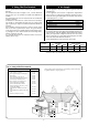
Fig. 17. Fixing the appliance to the wall mounting plate. Keep appliance vertical Appliance 7 1.Flue spigot fixing screws 2.Flue spigot 3.Restrictor ring 4.Flue spigot fixing holes 5.Combustion sensing point 6.Automatic air vent 7.Clamping ring 8.Fixing screw hole Step 3. Secure at bottom with caps and bolts supplied (3). Step 1. Rest appliance on wall mounting plate and push back, engaging valves first. Wall mounting plate Fig. 18. Flue turret fixing and automatic air vent. Step 2.
extends the flue by 750mm up to a maximum of 4m. See table below. EXTENSION MAXIMUM FLUE LENGTH mm 24CDi 28CDi 35CDi II 1 1475 1475 1475 2 2225 2225 2225 3 2975 2975 2975 4 3725 3000 3000 5 4000 Apply the plastic tape to the air duct in contact with the external brickwork. From inside push the assembly through the wall. Align the flue turret and push fully onto the spigot on the appliance. Tighten the clamping ring and fix using the screw provided. Refer to Fig.24. 12.9 Measure and Cut the Ducts.
12.12. Flue Bends. 90° and 45° bends are available. A maximum of two bends may be used in addition to the first bend on the flue turret. A 90° bend is equivalent to 750mm of straight duct. A 45° bend is equivalent to 375mm of straight duct. A maximum flue assembly of 3m is possible with 1 X 90° bend and 2m with 2 X 90° bends. Measure the lengths X,Y and Z. Refer to Fig.25. The maximum value of X using the turret assembly only is 506mm. Reduce the ducts to the appropriate length i.e.
between the gas cock and the gas valve, thus enabling the leak to be traced to either a visible joint or to the ‘O’ ring. 13.2 APPLIANCE AND CENTRAL HEATING SYSTEM PREPARATION Remove the cabinet front panel. Check that the electrical supply and the gas service to the appliance are off. Check that all the water connections throughout the system are tight. Open the system valves at the appliance. Open all the radiator valves, fill the system and vent each radiator in turn.
should be fitted as shown in Fig. 6,6a. Insert the bayonet end of the filling key into the corresponding cutouts in the filling loop housing and twist to lock the key in place. Turn the grey knob anti-clockwise to allow water ingress and fill until the pressure gauge reads 2.5 bar. Turn the grey knob clockwise to stop filling and remove the filling key by lining up the bayonet end of the key with the cutouts in the filling loop housing and withdrawing the key. N.B.
sensed by the control circuit. The burner pressure should be 14.8mbar (24CDi) or 15.5mbar (28CDi) or 13.5mbar (35CDi II) for natural gas and 35.5mbar (24/28CDi) or 34.7mbar (35CDi II) for propane. If the burner pressure cannot be achieved then check that the inlet pressure at the appliance is 20mbar for natural gas and 37mbar for propane. This is equivalent to a 18.5-19.0 mbar (G20) or 36 mbar (G31) at the gas valve. Set the gas valve mode switch to the minimum position.
Fig. 31. Appliance components and fixings (upper assembly). 15. Inspection And Servicing 15.1 SERVICING To ensure continued efficient operation of the appliance it must be checked and serviced as necessary at regular intervals. The frequency of servicing will depend upon the particular installation conditions and usage, but once per year should generally be adequate.
16. Replacement Of Parts Fig. 32. Burner and Electrode (24/28CDi shown) 16.1 SAFETY Switch off the electricity and gas supplies before replacing any components. After the replacement of any components, check for gas soundness where relevant and carry out functional checks as described in Section 13 - Commissioning 5-6mm Flame sensor detail 16.
Slacken the two screws to remove the two retaining brackets and lift the heat exchanger from the casing. Take care that the rear insulation pad does not drop forwards onto the burner. Fit the replacement heat exchanger in the reverse order ensuring that both the “O” rings are correctly fitted and lubricated and a layer of heat sink compound is on both the thermostats. Open the valves and fill and re-pressurise the system as described in Section 13.2. Fig. 33. Air pressure switch. 6.
10. Flame Sensor. Refer to Fig. 32. Remove the burner as described in Sections 15.3, h and 16.4.7. Undo the M3 screw and remove the sense electrode from the burner. Fit the replacement electrode in the reverse order, checking that the sense gap is 5 to 6mm. 11. Gas Valve. Refer to Fig. 28. Check that the electricity and gas supplies to the appliance are turned off. Hinge down the facia panel into the servicing position as described in Section 15.3, c.
12. Central Heating Sensor. Refer to Fig. 34. Remove the inner casing cover as described in Section 15.3, b. Check that the electricity supply to the appliance is turned off. Carefully pull off the two leads from the sensor. Pull off the sensor and spring retaining clip from the pipe. Fit the replacement sensor in reverse order with a layer of heat sink compound between the faces. Refit the leads. 13. Domestic Hot Water Sensor. Refer to Fig. 39.
18. Water Diverting Valve. See Fig. 36, 40. Check that the electricity supply to the appliance is turned off. Drain the central heating and domestic hot water circuits as described in Sections 16.3, a and b. Hinge down the facia panel into the Servicing Position as described in Section 15.3, c. Remove the bottom panel, filling loop, water to water heat exchanger and micro switch assembly as described in Section 15.3, d, and Sections 16.4.17, 20 and 22.
22. Filling Loop. Refer to Fig. 40. Check that the electricity supply to the appliance is turned off. Drain the central heating circuit as described in Section 16.3, a. Hinge down the facia panel into the servicing position as described in Section 15.3, c. Remove the screw securing the filling loop to the underside of the water diverting valve. Remove the clip retaining the filling loop to the plastic flow manifold.
17. Short Parts List Key No. G.C. No.
109 28
18. Operational Flow Diagrams Room thermostat and/or mains programmer (or link) On AND AND Electronic facia programmer (if fitted) On AND ST13 link in AND CH control knob On CENTRAL HEATING FUNCTION MAIN SWITCH ON CENTRAL HEATING DEMAND Green Light On CH light On. Pump On. Fan ON High for 2 sec then Low speed 28CDi. Fan ON High for 2 sec then Low speed 35CDi II. Ignition Sequence. Burner Light On.
OVERRUN FUNCTION Within four minutes of last hot water demand AND AND primary temperature above 80°C If heat demand has occurred in last 30 minutes Run pump until primary drops to 80°C If heat demand has NOT occurred in last 30 minutes Run fan until primary drops to 80°C If primary temperature still increases above 90°C Run pump for two seconds (Pulse pump for 2 seconds every 10 seconds 35CDi II) AUTOFROSTAT FUNCTION No demand and primary temperature below 8°C Internal “Autofrostat” demand Wait i
19. Fault Finding Note: This fault-finding information is for guidance only. Worcester Heat Systems cannot be held responsible for costs incurred by persons not deemed to be competent. The electronic control system for this boiler incorporates four lights on the facia. These are used to show normal operating status. But as a secondary function, by flashing, they can also be used to help provide fault diagnostics.
Is the facia on/off switch turned on? `(Clockwise) No Turn switch on. FAIL POINT A Yes Is there a 230V AC live supply across Terminal ST12 pins L and N No Check electrical supply to boiler. Yes Has fuse F1 blown? No Replace control board (Section 16.4.23) Yes Replace fuse and investigate cause. Suggestions: Cable damage, connections to (or faults within) pump, fan, external 230V controls, transformer or board. FAIL POINT B Has fuse F2 blown? No Yes Replace fuse.
With CH control knob fully clockwise, does the boiler ignite and appear to run normally in central heating mode? No Is there 230V AC across terminal ST8 pins LR and N? No There is no heat demand. Check room thermostat or mains programmer (or link). Yes Yes Red diode is damaged. Replace control board. (Section 16.4.
FAIL POINT F Is the boiler in a very cold environment (less than 5°C)? No Yes No Yes Replace control board. (Section 16.4.23). Note: A wet board could cause this fault. Boiler is running in “Autofrost stat” mode. See Section 18. Is the boiler fully water pressurised and is all air vented? Drop down the facia. Is the gas valve mode switch in the normal position? No Rectify fault. Yes FAIL POINT G “Primary Overheat” Reset the controls and restart the boiler.
Is the gas supply connected and at the correct inlet and outlet pressures? No Rectify gas supply problem. Yes Remove front panel. Reset and restart the boiler. Can a flame be seen through the spy glass? No Remove inner cover. Reset and restart the boiler. Does a spark occur across the electrodes? No Are the electrodes and gap and connections in good order? No Repair or replace spark electrode (Section 16.4.9) or HT leads Yes Replace control board. (Section 16.4.23). Yes Turn off boiler.
Is the multiway connector at board position ST16 pushed fully home on to the board? No Push fully home. Yes Remove multiway connector from board position ST16. Test resistance across contacts 17 and 18 (yellow wires). Is it between 1 kohm and 30 kohm? No FAIL POINT I “Sensor Fault” No Repair or replace harness. Yes Check or replace DHW sensor. (Section 16.4.13). Yes Test resistance across contacts 12 and 13 (red wires).
Does this fault occur in only one of the operating modes? CH or DHW Remove fan connector from board position ST1 and restart boiler in the fault mode. After 5 seconds is there mains 230V from the left (N) track at ST1 and right (L) track if DHW mode? Centre (L) track if CH mode? Replace control board (Section 16.4.23). Repair or replace fan (Section 16.4.3) or cable. 28CDi and 35CDi II 24CDi,28CDi and 35CDi II Replace control board (Section 16.4.23).
FAIL POINT K Light indication during fault not covered by above details. Control board is likely to be wet or damaged or malfunctioning. Check for wet board or connections. Dry and re-use or replace control board. (Section 16.4.13). Hot water temperature always too hot during a demand (not regulating). Hot water sensor could be off or poorly fixed to pipe. Repair or replace sensor. (Section 16.4.14).
20. Conversion Instructions GAS VALVE Max 2mm Allen key ONLY COMPONENTS SUPPLIED BY WORCESTER HEAT SYSTEMS SHOULD BE USED. ONLY COMPETENT PERSONNEL SHOULD ATTEMPT THE CONVERSION. CONVERSION FROM NATURAL GAS TO LPG SHOULD NOT BE CARRIED OUT ON APPLIANCES INSTALLED IN A ROOM OR INTERNAL SPACE BELOW GROUND LEVEL Min 3mm Allen key 1 Conversion Kit LPG to NG Conversion Kit NG to LPG 7 716 192 307 7 716 192 308 1. Ensure the gas service cock is turned OFF and the electrical supply is ISOLATED. 2.
This manual is to be used in conjunction with the variant part number of the bar code below: 24CDi 28CDi 35CDi II Worcester Heat Systems Limited (Bosch Group), Cotswold Way, Warndon, Worcester WR4 9SW. Telephone: 01905 754624. Fax: 01905 754619. Technical Helpline 08705 266241. www.worcester-bosch.co.uk This booklet is accurate at the date of printing but will be superseded and should be disregarded if specifications and/or appearances are changed in the interests of continued improvement.