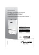
USER INSTRUCTIONS WALL HUNG RSF GAS FIRED CONDENSING SYSTEM BOILER Greenstar i System Compact FOR CENTRAL HEATING SYSTEMS AND INDIRECT MAINS FED DOMESTIC HOT WATER 6720643358-00.1Wo These appliances are for use with : Natural Gas or L.P.G. (Cat. II 2H 3P type C13, C33 & C53) Model GC Number Natural Gas 27i System Compact 41-406-13 30i System Compact 41-406-15 27i System Compact 41-406-14 30i System Compact 41-406-16 L.P.G.
PREFACE PREFACE PLEASE READ THESE INSTRUCTIONS CAREFULLY These instructions are applicable to the Worcester, Bosch Group boiler model stated on the front cover only. These instructions apply in the UK/IE only and must be followed except for any statutory obligation. After installation please leave this User instruction Manual, Installation, Commissioning and Servicing Instructions and completed Benchmark Checklist with the user.
CONTENTS CONTENTS 1 Symbols and safety precautions . . . . . . . . . . . . . . . . . . . . . . . . . . . . . . . . . . . 4 1.1 Explanation of symbols . . . . . . . . . . . . . . . . . . . . . . . . . . . . . . . . . . . . . 4 1.2 Safety precautions . . . . . . . . . . . . . . . . . . . . . . . . . . . . . . . . . . . . . . . . 5 2 General Information . . . . . . . . . . . . . . . . . . . . . . . . . . . . . . . . . . . . . . . . . . . . . 6 3 Controls . . . . . . . . . . . . . . . . . . . . . . . . .
SYMBOLS AND SAFETY PRECAUTIONS 1 SYMBOLS AND SAFETY PRECAUTIONS 1.1 EXPLANATION OF SYMBOLS WARNING SYMBOLS Safety instructions in this document are framed and identified by a warning triangle which is printed on a grey background. Signal words indicate the seriousness of the hazard in terms of the consequences of not following the safety instructions. • NOTICE indicates possible damage to property or equipment, but where there is no risk of personal injury. • CAUTION indicates possible personal injury.
SYMBOLS AND SAFETY PRECAUTIONS 1.2 SAFETY PRECAUTIONS IF YOU SMELL GAS A gas leak could potentially cause an explosion. If you smell gas, observe the following rules. ▶ Prevent flames or sparks: – Do not smoke, use a lighter or strike matches. – Do not operate any electrical switches or unplug any equipment. – Do not use the telephone or ring doorbells. ▶ Turn off the gas at the meter or regulator. ▶ Open windows and doors. ▶ Warn your neighbours and leave the building.
GENERAL INFORMATION 2 GENERAL INFORMATION SERVICING Ensure that the service engineer completes the Service Record in the Benchmark Checklist after each service. The Benchmark Checklist and service interval record can be found at the rear of the Installation, Commissioning and Servicing Instructions. • The boiler must be serviced regularly by a competent, qualified person, such as a Worcester service engineer or other Gas Safe registered engineer.
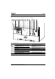
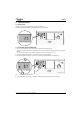
CONTROLS 3 CONTROLS ▶ To gain access to the boiler controls pull the flap down using the curved flap handle. 1 2 3 4 5 6 7 8 9 10 11 12 13 14 67 Fig. 1 20 64 33 58 02 .1 o W Basic boiler controls Boiler Controls 1 Service menu/back button 9 2 Service engineer symbol = boiler is set to maximum or minimum output for service 10 The blue light is ON when the boiler is in an operational mode. It will also flash to indicate a fault.
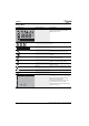
CONTROLS DISPLAY SYMBOLS SCREEN DISPLAY BRIEF DESCRIPTION EXPLANATION All possible screen symbols This screen is displayed briefly during boiler start up and shows all the symbols that could be displayed on the screen. Numerical display Displays a temperature setting or boiler status code. Text display Display PreHeat or Eco, or the Alert code Hot water Displays this symbol during a DHW demand, if the optional integral diverter valve kit is fitted.
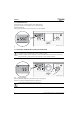
CONTROLS 3.1 OPERATING THE BOILER 3.1.1 BOILER DISPLAY This is typical of the display when the boiler is not supplying a heat demand. The display will not be backlit and the internal temperature of the boiler is indicated. eco 2 °C reset 1 ok °F 0 3 bar 4 min °F max min 6720807727-01.1Wo e °C max 3.1.2 SETTING THE BOILER FLOW TEMPERATURE 1. Turn the central heating temperature control knob to the desired flow temperature between 30 and 82°C, this will be indicated on the digital display.
CONTROLS 3.1.3 BOILER FLOW FUNCTION If a heat demand occurs, the radiator and flame symbols will be displayed If the domestic hot water control is adjusted or the “eco” button is pressed: ▶ N/A is displayed briefly. ▶ If the optional integral diverter valve is fitted, PreHeat or Eco will be displayed. eco °C reset °F 2 1 ok 3 0 bar 4 e °C °F min max min max 6720807727-05.1Wo Fig. 3 3.1.
CONTROLS 3.1.5 DOMESTIC HOT WATER PRE-HEAT ▶ The hot water cylinder (when selected by the timer) is heated more regularly to reduce the time taken to deliver hot water. Pre-heat is enabled by default, during the initial boiler start up and the text “PreHeat” will be displayed to confirm this state. ▶ If a cylinder demand occurs, the tap and flame symbol will be displayed. An external timer may be fitted. eco 2 °C reset 1 ok °F 0 Preheat 3 bar 4 e °C °F min max min max PreHeat 6720807727-04.
CONTROLS 3.1.7 BOILER ALERT STATE In the event of an alert, a fault code and an alert symbol will be displayed on the boiler display and the blue operation/fault light will flash. Refer to the Fault finding section on page 17 or press Reset reset to clear the problem. eco 2 °C reset 1 ok °F 0 227 3 bar 4 min °F max min 6720643358-14.1Wo e °C max 227 Fig. 7 Alert state 3.1.8 BOILER RESET 1. To reset the boiler, press the reset button reset . 2.
CONTROLS 3.1.9 TURNING THE CENTRAL HEATING OFF DURING THE SUMMER ▶ Turn your programmer/timer to the off position. ▶ Please refer to the programmer/timer manufacturer's instructions. 3.1.10 BOILER FROST PROTECTION NOTICE: The boiler must be switched on with a gas supply in order for the built -in auto frost protection to work as described. If you are leaving your property unoccupied during cold weather, please leave your programmer on constant and your room thermostat set to 15°C.
SYSTEM PRESSURE 4 SYSTEM PRESSURE 4.1 SEALED HEATING SYSTEMS This boiler is fitted to a sealed heating system which is pre-pressurised. Your installer will advise you of the minimum and maximum pressure indicated on the pressure gauge. ▶ Check regularly that the pressure is maintained. 1.5 bar Max 2 1 3 Min 0 Fig. 9 bar 4 6720643356-11.
SYSTEM PRESSURE 4.2 EXTERNAL FILLING LOOP NOTICE: External filling loops ▶ If the filling loop does not look like the one shown in the figure below or you cannot find your filling loop, contact your installer. Once the external filling loop has been located, follow the instructions for re-pressurising the system. 1. Unscrew blanking cap. 2. Attach the hose to the valves, screw on hand-tight. 3. Turn the handle/screwdriver slot through 90° to open the valves. 4.
SERVICE CLEARANCES 5 SERVICE CLEARANCES Your installer will have provided adequate space around the boiler for safety and servicing access. CAUTION: Restricted space. The boiler may overheat. ▶ Do not restrict this space with the addition of cupboards, shelves etc. next to the boiler. 880mm 170/210mm*** 600mm** 5mm 5mm 200mm 400mm Fig. 11 * 300mm 6720646608-122.
FAULT FINDING 7 FAULT FINDING In the event that the boiler stops functioning or does not perform as expected, you can carry out a few simple checks. These checks are some of the most common causes and are listed in the table below. Should the problem persist or other alert codes are displayed, then it will be necessary to contact the Worcester, Bosch Group. Problem Cause Remedy EA fault code flashing on display No gas supply/low gas supply pressure ▶ Contact your gas supplier.
FAULT FINDING ALERT CODES If the blue operation/fault indicator light on the front of your boiler is flashing and a warning triangle code on the screen, e.g. EA, reset your boiler, refer to page 12. is displayed with an alert Press the Reset button reset for approximately one second, if the reset has been successful the word “Reset” will be displayed with the tick mark to confirm that the reset was successful.
FAULT OR BREAKDOWN 8 FAULT OR BREAKDOWN This boiler is supported in the UK and Eire by Worcester, Bosch Group. Specialist Service Engineers are available to attend a breakdown occurring on this boiler. Invoices for attendance and repair work carried out on this boiler by any third party will not be accepted. • No charge will be made for parts and/or labour providing: A boiler fault is found and the appliance has been installed within the last 24 months.
TIPS ON ENERGY SAVING 10 TIPS ON ENERGY SAVING HEATING ECONOMICALLY The boiler provides a high level of comfort whilst keeping gas consumption and the environment effects as low as possible. The gas supply to the burner is controlled according to the level of demand for heat. The boiler operates with a low flame if the demand for heat reduces. The technical term for this process is modulating control.
YOUR GUARANTEE 11 YOUR GUARANTEE This boiler has a guarantee against faulty materials or workmanship for a period of 2 years from the date of installation subject to the following terms and conditions: • During the period of this guarantee any components of the boiler which are proven to be faulty or defective in manufacture will be exchanged or repaired free of charge by Bosch Thermotechnology Ltd.
GLOSSARY 12 GLOSSARY Central heating systems All radiators must be heated at an even rate. If the top of a radiator is at a lower temperature than the bottom then it should be bled by releasing air through the bleed screw at the top of the radiator. Ask your installer to show you how this is done. This boiler is fitted to a sealed system. Should water leaks be found or if excessive bleeding is required, then a service engineer must be contacted to inspect the installation and rectify any fault.
NOTES Greenstar i System Compact – 6 720 807 727 (2013/05) 23
WORCESTER, BOSCH GROUP: Worcester, Bosch Group Cotswold Way, Warndon, Worcester WR4 9SW. Tel. 0844 892 9900 Worcester, Bosch Group is a brand name of Bosch Thermotechnology Ltd. worcester-bosch.co.uk Document No.