
Technical Specifications
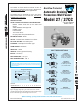

Backflow Protected
Automatic Draining
Freezeless Wall Faucet
Model 27 / 27CC
SPECIFICATIONS:
HOSE CONNECTION BACKFLOW PREVENTER –
· NIDELâ Model 37HA with ¾ inch male hose
thread
· ASSE Standard 1052 approved
· IAPMOâ listed
· Field Testable
· Two check valves
· No spray-back with pressurized hose
EXTERIOR FINISH - Brass
VALVE – Molded nitrile suitable for hot water.
NO LEAD SOLDER - All solder joints.
PLUNGER – Hemispherical cushion type.
STEM SCREW – DELRINâ
HEAD NUT – Brass
HANDLE – Metal. (Optional tee Key)
INLETS – As shown.
MAX PRESSURE – 125 p.s.i.
MAX TEMPERATURE - 120° F
90
09
WOODFORD MFG. CO.WOODFORD
MFG.
CO.
15
p
VALVES
90
09
VALVES - freezelessVALVES -
freezeless
WOODFORD MFG. CO.WOODFORD MFG. CO.
15
p
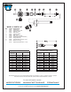
When ordering, specify model number, inlet, and wall thickness.
©2003 WOODFORD Mfg.
Rev. 02/03 Form No. 27.103
Approx. Shipping Weight (lbs.) per master carton of ten faucets.
*Overall Length Dimension:Add wall thickness and inlet option length
shown in chart at the right. Overall length for 27CC is 2 3/4”.
The Model 27 faucet drains as handle is shut off
even if hose is attached
. This faucet is designed for
residential outside water service applications.
WOODFORD
NOTICE - To close and drain, turn handle clockwise until
seated and water drains out of drain hole or faucet may freeze
and burst. Backflow Preventer replacement is recommended
every 3-5 years.
For Non-Freeze
Areas ONLY
The Model 27CC is designed for use in non-freeze
areas and fits within 2” X 4” stud wall. The 27CC is
available with C Inlet only.
Model 27
W all Thickness
CC
4 6 8 10 12 14 16 18 20 22 24
Shipping Wt. 22 22 23 24 25 26 27 29 31 33 35 37
Rough-In Dimensions
*OVERALL LENGTH
SEE
INLET
WALL
ALIGNING MARK
P Inlet
COMBINATION
1/2” Female Pipe Thread
3/4” Male Pipe Thread
C Inlet
COMBINATION
Copper Sweat Fitting
1/2” K, L or M Inside
3/4” M Only Outside
CP3 Inlet
COMBINATION
3/4” Male Pipe Thread
3/4” Female Sweat
CP Inlet
COMBINATION
1/2” Male Pipe Thread
1/2” Female Sweat
PX Inlet
1/2” PEX Tube Fitting
1 5/81 5/8
15/16
1 7/81 7/8
1 1/161 1/16
1 7/81 7/8
1 1/161 1/16
1 3/41 3/4
15/16
1 3/41 3/4
15/16
INLET DESCRIPTIONS