
Technical data


Mountain Series CE
Installation and Operation Manual
12
An ongoing program of product improvement may require us to change
specifications without notice. WS-MS-(RFG, RFG-IR)-CE,
Revised May 2014 Doc no: M0037.01
info@woodstone-corp.com or visit woodstone-corp.com
wood stone corporation
1801 w. bakerview rd.
bellingham, wa 98226 usa
t. +1.360.650.1111
f. +1.360.650.1166
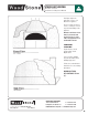
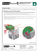
EXTENSION PANEL ASSEMBLY
OPTIONAL LOWER EXTENSION, THROTTLE ROD AND CONTROLLER ASSEMBLY INSTRUCTIONS
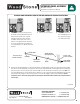
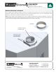
7. CALIBRATING THE POINTER
Loosen the pointer collar set screws using a 3/16" Allen wrench�
Position the attached pointer to “5” on the Flame Height Index
Scale� Tighten the pointer collar in this position� Make certain
the tip of the pointer is at least 3 mm (1/8") away from the index
scale at the tightest point of the rotation of the knob so it does
not scrape�
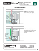
5. Pass the throttle rod through the throttle bracket (already attached)� Position the pointer
in approximately the 2 o’clock position� Slide the clamp on the EMT over the end of the
throttle rod/knob assembly and Attach the throttle rod to the EMT throttle rod extension
using the compression clamp� On curved façade extensions, make to leave at least 3
mm (1/8") of space between the end of the pointer and the bracket when it is set to a
horizontal position�
6. Reinstall the front panel� Secure the controller with a 1/4-20 screw at the top and bottom�
Use (2) #10 stainless steel sheet metal screws to secure the front panel to the throttle
bracket�
Pointer collar set screws
3 mm (1/8")
minimum clear-
ance