
Technical data
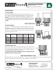


Mountain Series CE
Installation and Operation Manual
10
An ongoing program of product improvement may require us to change
specifications without notice. WS-MS-(RFG, RFG-IR)-CE,
Revised May 2014 Doc no: M0037.01
info@woodstone-corp.com or visit woodstone-corp.com
wood stone corporation
1801 w. bakerview rd.
bellingham, wa 98226 usa
t. +1.360.650.1111
f. +1.360.650.1166
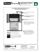
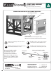
FRONT PANEL ASSEMBLY
Service panel throttle assembly
The throttle knob position can be
adjusted inward or outward by
loosening the clamp and sliding the
throttle knob assembly to the desired
position� Be sure to retighten the clamp
once the throttle knob is in the desired
position�
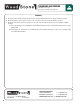
STANDARD FRONT PANEL AND TOE KICK ASSEMBLY INSTRUCTIONS
A Hex-head self-tapping screw� Used to attach
toe kick� 4 total�
B Phillips head 1/4-20 screw� Used to attach
service panel to controller bracket� 2 total�
C Phillips head #10 screw� Used to attach service
panel to throttle knob bracket� 2 total�
D Phillips head self-tapping screw� Used to
secure the sides of the service panel� 8 total�
D
D
B
D
D
B
D
D
D
D
C
C
A
A
Controller
Flame Height Control Knob
Transformer Box
Contains terminal strip for incoming power supply.
NOTE: Have licensed electrician make this electrical connection
Service Panel
Cotter key
Flame Height
Control Knob
Throttle bracket
Pointer
collar/
Pointer
Clamp
EMT throttle rod
extension
Throttle valve
Cotter pin
Service panel throttle assembly
FRONT PANEL ASSEMBLY