KEEP FOR FUTURE REFERENCE INSTRUCTIONS International Version P.O.
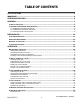
TABLE OF CONTENTS SPECIFICATIONS ............................................................................................................ 3 WARNINGS ..................................................................................................................... 4 OPERATING FEATURES ................................................................................................... 5 ASSEMBLY .............................................................................................................
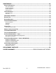
MAINTENANCE ............................................................................................................. 24 INSPECTION SCHEDULE ............................................................................................................. 24 Every-Lift Inspection ..................................................................................................................................24 Frequent Inspection ...............................................................................
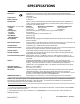
SPECIFICATIONS Model Number: MTCL8HV11FDC Description: Designed for use with a crane or other hoisting equipment, the MTCL8HV11FDC lifter employs vacuum to hold a load for lifting, and it provides manual 90° tilt movements for load manipulation.
WARNINGS Powr-Grip is pleased to offer the most reliable vacuum lifters available. Despite the high degree of security provided by this product, certain precautions must be observed to protect the operator and others. Always wear personal protective equipment that is appropriate for the material being handled. Follow trade association guidelines. Always operate the lifter under conditions approved for its design (see INTENDED USE: OPERATING ENVIRONMENT).
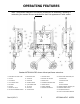
OPERATING FEATURES Note: Components featured in the following instructions for assembling, operating or maintaining the vacuum lifter are underlined on their first appearance in each section. Standard MTCL8HV11FDC shown without pad frame extensions.
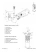
OPTIONAL REMOTE CONTROL SYSTEM 1 RADIO RECEIVER 2 RADIO TRANSMITTER 3 STROBE LIGHT 4 VACUUM LIFT LIGHT 5 ENABLE BUTTON 6 APPLY BUTTON 7 RELEASE BUTTON OPTIONAL RADIO TRANSMITTER 1 TRANSMISSION INDICATOR LIGHT 2 TRANSMITTER POWER/ENABLE BUTTON 3 RELEASE BUTTONS 4 APPLY BUTTONS 5 EMERGENCY TRANSMITTER DISCONNECT Rev 6.
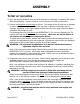
ASSEMBLY TO SET UP THE LIFTER 1) Open the shipping container and remove all materials for restraining or protecting the vacuum lifter during shipping. Save the container for use whenever the lifter is transported. 2) Position the adjustable lift point tube as follows: The location of the lift point can be adjusted to obtain the optimal hang angle of the lifter and load.
4) To use the movable control pendant (instead of the optional Remote Control System), insert the plug of its coiled cord into the controls receptacle on the power system enclosure. Then secure the connector by tightening its threaded collar. 5) Assemble the pad frame in the configuration that will provide optimal support of the load while lifting (see TO CHANGE THE PAD FRAME CONFIGURATION to follow).
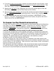
Pad Spread and Maximum Load Capacity (larger configurations shown with pad frame extensions) Rev 6.
To Install/Remove Pad Frame Extensions 1) Insert the end of a pad frame extension in one socket on the main pad frame, so that the holes align for the cotterless hitch pin. 2) Secure the pad frame extension in the pad frame by pushing a cotterless hitch pin through the holes until the retaining ball emerges on the far side of the pad frame socket. 3) Use the quick connectors to connect the vacuum hoses from the pad frame extensions to the main pad frame as directed in the discussion to follow.
INTENDED USE LOAD CHARACTERISTICS WARNING: This lifter is NOT intended for lifting hazardous materials, such as explosives or radioactive substances. The operator must verify that the lifter is intended to handle each load, in accordance with the following requirements: • The load must not exceed the maximum allowable weight specified under Load Capacity (see SPECIFICATIONS). • The load must be a single piece of nonporous or semiporous material with a flat and relatively smooth contact surface.
OPERATING ENVIRONMENT The operator must determine whether the lifter is intended to be used in each work environment, in accordance with the following restrictions: WARNING: Never use lifter in dangerous environments. • This lifter is not intended for use in any environment that is inherently dangerous to the operator or likely to compromise the lifter's ability to function. Environments containing explosives, caustic chemicals and other dangerous substances must be avoided when using the lifter.
TYPICAL APPLICATIONS Though the lifter is designed with the flexibility to be used in many different ways, these illustrations represent some typical applications. Rev 6.
OPERATION BEFORE USING THE LIFTER The operator must determine whether the lifter is capable of performing each intended task, in accordance with the SPECIFICATIONS and INTENDED USE sections of this INSTRUCTIONS manual. In addition, all of the following preparations must be completed prior to lifting any load. Taking Safety Precautions The operator must be trained in all relevant industry and regulatory standards for the operation of the vacuum lifter in its geographical location (eg, ASME B30.
CAUTION: Examine each air filter regularly, and empty when necessary. Two air filters help protect the vacuum generating system from contaminants. However, the lifter is not intended for use on wet load surfaces because the filters would not necessarily prevent liquid from entering the vacuum system. In order for a filter to function, the operator must empty the filter bowl before enough liquid accumulates to contact any portion of the filter element (see MAINTENANCE: AIR FILTER MAINTENANCE).
If the lifter is equipped with a Remote Control System, press the transmitter power/enable button and hold it briefly to activate the radio transmitter.6 This button is also used to activate the enable function (see TO RELEASE THE PADS FROM THE LOAD to follow).
Sealing the Pads against the Load The apply/release switch is located on the movable control pendant. The movable control pendant allows the vacuum controls to be moved away from the lifter, so that the operator can control airflow at a distance equal to the length of the pendant cord. WARNING: Do not disconnect control pendant during lifter operation. The movable control pendant is not intended to be disconnected during lifter operation.
Vacuum Level on Optimal Surfaces When the lifter is attached to clean, smooth, nonporous load surfaces, it should be able to maintain a vacuum level in the green range on both vacuum gauges, except when used at high elevations (see SPECIFICATIONS: Operating Elevation). If not, make sure the vacuum switches are adjusted correctly (see MAINTENANCE: VACUUM SWITCH ADJUSTMENT).
TO LIFT AND MOVE THE LOAD Positioning the Lift Bar WARNING: Lift bar must be oriented vertically to lift load. Never lift the load from a flat position with the lift bar latched parallel to the load. Always disengage the tilt latches (see TO TILT THE LOAD to follow) and raise the lift bar to a vertical orientation before attempting to lift. Interpreting the Warning Buzzer and Lift Light A lifter’s Load Capacity is rated at a vacuum level of 16" Hg [-54 kPa] (see SPECIFICATIONS).
Controlling the Lifter and Load When vacuum indicators show that the lifter is ready, use the hoisting equipment to raise the lifter and load as needed to clear any obstacles in their path. Use the control handles or other appropriate means to keep the lifter and load in the desired orientation while they are suspended from the crane. WARNING: When lifter is positioned above center, tilt latches must be locked out before lifting load.
TO TILT THE LOAD WARNING: Make sure load is positioned correctly on lifter (see TO APPLY); unbalanced loads may tilt unexpectedly when latches are disengaged. The tilt feature allows the operator to transfer a load from the flat position to the upright position, and vice versa (see INTENDED USE: TYPICAL APPLICATIONS). Remember that the load requires more vertical space when tilting to the upright position, as well as more horizontal space when tilting to the flat position.
time during the tilt: To lock out the tilt latches, push the tilt control lever all the way upward until it locks in the disengaged position. Whenever tilt is not required, keep the tilt latches engaged, to prevent accidental damage to the load and possible injury to the operator. TO RELEASE THE PADS FROM THE LOAD WARNING: Load must be fully supported before releasing vacuum pads.
AFTER USING THE LIFTER Leave the apply/release switch in the neutral position and place the power switch in the OFF ( ) position (power light shuts off when power is disengaged). CAUTION: Do not set the lifter against any surfaces which could soil or damage the vacuum pads. To remove the lifter from the hoisting equipment, place stable supports under the center of the pad frame. Additional supports may be placed under the pad frame extensions for stability.
MAINTENANCE WARNING: Always make sure battery is disconnected before servicing lifter. Note: One or more wiring/hose routing diagrams are provided in the final section of this INSTRUCTIONS manual for reference when servicing the lifter or trouble-shooting a deficiency. INSPECTION SCHEDULE Perform inspections routinely, according to the following frequency schedule: Every-Lift Inspection • Examine the vacuum pads and load surface for contamination or debris (see VACUUM PAD MAINTENANCE to follow).
• Keep a written record of all Periodic Inspections. If any deficiency is detected during the inspection, correct it before using the lifter. If necessary, return the lifter to Wood’s Powr-Grip or an authorized dealer for repair (see LIMITED WARRANTY). Infrequent Use If a lifter is used less than 1 day in a 2-week period, perform the Periodic Inspection each time before using the lifter.
MAINTENANCE SCHEDULE Unless specified elsewhere in this INSTRUCTIONS manual, the lifter does not require maintenance on a routine basis. Instead, maintenance must be performed whenever a deficiency is indicated by routine inspections or tests. Any maintenance warranted must be performed before resuming normal operation of the lifter. BATTERY TEST The lifter is equipped with a battery gauge to help the operator evaluate whether the battery has adequate energy for lifting.
Temperatures higher than 70° Fahrenheit [21° Celsius] require the battery to be charged more frequently. Identify the input voltage marked on the power system enclosure, plug the charger cord supplied into the charger cord receptacle and plug the other end into an appropriate power source.13 The power source must be equipped with a ground fault circuit interrupter, in order to reduce the risk of electrical shocks. WARNING: Power source must be equipped with ground fault circuit interrupter.
The Load Capacity of most Powr-Grip lifters is based on a friction coefficient of 1 (only Flat Lifters are exempt from this requirement). However, a vacuum pad's ability to maintain this friction coefficient is reduced by factors such as contamination, wear, age and exposure to sunlight, as well as the condition of the load's contact surface (see INTENDED USE: LOAD CHARACTERISTICS). Pads that have surface contamination must be thoroughly cleaned (see Cleaning discussion to follow).
clinging to sealing edges.16 Wipe all residue from the pad face, and allow the pad to dry completely before using the lifter. VACUUM TEST Test the vacuum system for leakage routinely, as directed in the preceding INSPECTION and TESTING SCHEDULES. 1) Clean each vacuum pad as previously directed (see VACUUM PAD MAINTENANCE: Cleaning). 2) Apply the lifter to a clean, smooth, nonporous surface. The surface should be flat or possess no more curvature than the lifter is designed for (if any).
REMOTE CONTROL SYSTEM TEST If the lifter is equipped with a Remote Control System, perform this test in the environment where the lifter is normally employed. Use the radio transmitter to activate each of the remote functions.18 Vary the location and distance of the transmitter in relation to the lifter, to ensure that transmissions are effective in a variety of circumstances. This may require assistance from someone near the lifter, to verify that functions are being performed as intended.
TILT LATCHES ADJUSTMENT If it becomes difficult to disengage or lock out the tilt latches (see OPERATION: TO TILT THE LOAD: Operating the Tilt Latches), the tilt latch mechanism requires adjustment, as follows: When the tilt latches are engaged, the cable should remain taught but should not retract the latch pins at all. To change this adjustment, remove the flat head socket screw from the adjustment clevis in one of the tilt latches and remove the cable from the clevis.
AIR FILTER MAINTENANCE − LARGE (for 4.4 oz [130 ml] bowl size filters) Filter Function and Conditions Requiring Service An air filter prevents solid particles and liquid from contaminating components in the vacuum system. CAUTION: Examine air filter regularly and empty when necessary. Liquid must not contact any portion of the filter element; remove trapped liquid regularly.
VACUUM PUMP MAINTENANCE − DYNAFLO DV1032102 WARNING: Before proceeding with any maintenance, disconnect power source. If the vacuum pump takes too long to attain full vacuum, it may require maintenance. Replace the diaphragm, gasket/flap valves or (when preferable) the entire head assembly19 (see REPLACEMENT PARTS LIST), as necessary to obtain acceptable pump performance. CAUTION: Do not over-tighten the head screws, because this may damage the threads in the pump body.
VACUUM SWITCH ADJUSTMENT Vacuum Switch Function Two vacuum switches control various functions of the vacuum lifter (see OPERATING FEATURES for location of vacuum switches). While the lifter is powered up, each vacuum switch senses the vacuum level in one of the two vacuum circuits of the vacuum system. If either circuit loses significant vacuum while the lifter is in the apply mode, the system responds automatically.
• n_3 = -422. This setting turns off the low vacuum warning buzzer, light and/or strobe light and turns on the vacuum lift light, indicating that the lifter has already reached the minimum vacuum level (see n_4). Setting n_3 must always be set above n_4. • n_4 = -419. After the vacuum switch has turned off the vacuum pump(s) (see n_1) and the vacuum system has lost significant vacuum, setting n_4 turns on the low vacuum warning buzzer, light and/or strobe light and turns off the vacuum lift light.
REPLACEMENT PARTS LIST Stock No.
LIMITED WARRANTY Powr-Grip products are carefully constructed, thoroughly inspected at various stages of production, and individually tested. They are warranted to be free from defects in workmanship and materials for a period of one year from the date of purchase. If a problem develops during the warranty period, follow the instructions hereafter to obtain warranty service. If inspection shows that the problem is due to defective workmanship or materials, Powr-Grip will repair the product without charge.
Rev 6.
Rev 6.
Rev 6.