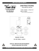
KEEP FOR FUTURE REFERENCE INSTRUCTIONS International Version P.O.
SPECIFICATIONS Model Number: MT5HV11DC Description: Designed for use with a crane or other hoisting equipment, the MT5HV11DC lifter employs vacuum to hold a load for lifting, and it provides manual 90° tilt movement for load manipulation.
WARNINGS Powr-Grip is pleased to offer the most reliable vacuum lifters available. Despite the high degree of security provided by this product, certain precautions must be observed to protect the operator and others. Always wear personal protective equipment that is appropriate for the material being handled. Follow trade association guidelines. Always operate the lifter under conditions approved for its design (see INTENDED USE: OPERATING ENVIRONMENT).
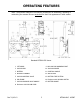
OPERATING FEATURES Note: Components featured in the following instructions for assembling, operating or maintaining the vacuum lifter are underlined on their first appearance in each section. Standard MT5HV11DC shown.
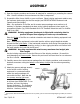
ASSEMBLY 1) Open the shipping container and remove all materials for restraining or protecting the vacuum lifter. Save the container for use whenever the lifter is transported. 2) Suspend the lifter from a forklift or crane as follows: Select hoisting equipment rated to carry the maximum load weight plus the lifter weight (see SPECIFICATIONS: Maximum Load Capacity and Lifter Weight).
equipment design and applicable statutory or regulatory standards must be factored into any specific installation. Consult the hoisting equipment manufacturer to determine how to mount the vacuum package in a safe location that does not interfere with hoisting equipment operation. 5) Inspect the vacuum line that runs from the lifter to the vacuum package: Make certain the vacuum line is routed so that it does not become tangled, kinked, pinched or cut while operating the lifter or hoisting equipment.
INTENDED USE LOAD CHARACTERISTICS WARNING: This lifter is NOT intended for lifting hazardous materials, such as explosives or radioactive substances. The operator must verify that the lifter is intended to handle each load, in accordance with the following requirements: • The load must not exceed the maximum allowable weight specified under Load Capacity (see SPECIFICATIONS). • The load must be a single piece of nonporous or semiporous material with a flat and relatively smooth contact surface.
OPERATING ENVIRONMENT The operator must determine whether the lifter is intended to be used in each work environment, in accordance with the following restrictions: WARNING: Never use lifter in dangerous environments. • This lifter is not intended for use in any environment that is inherently dangerous to the operator or likely to compromise the lifter's ability to function. Environments containing explosives, caustic chemicals and other dangerous substances must be avoided when using the lifter.
OPERATION BEFORE USING THE LIFTER The operator must determine whether the lifter is capable of performing each intended task, in accordance with the SPECIFICATIONS and INTENDED USE sections of this INSTRUCTIONS manual. In addition, all of the following preparations must be completed prior to lifting any load. Taking Safety Precautions The operator must be trained in all relevant industry and regulatory standards for the operation of the vacuum lifter in its geographical location (eg, ASME B30.
TO APPLY THE PADS TO A LOAD Positioning the Lifter on the Load Make certain that the contact surfaces of the load and all vacuum pads are free of any contaminates that could prevent the pads from sealing against the load (see MAINTENANCE: VACUUM PAD MAINTENANCE). Center the lifter’s pad frame to within 2" [5 cm] of the load center, since off-center loading can cause the load to tilt unexpectedly (see TO TILT THE LOAD to follow), and it may also damage the lifter.
Reading the Vacuum Gauge The vacuum gauge indicates the current vacuum level in the lifter’s vacuum system. The gauge needle should show a sudden surge in vacuum as the vacuum pads seal against the load. If it takes more than 5 seconds for the vacuum level to reach 5" Hg [-17 kPa], press on any pad that has not yet sealed. The lifter's Load Capacity is rated at a vacuum level of 17½" Hg [-59 kPa] (see SPECIFICATIONS).
TO LIFT AND MOVE THE LOAD Load Capacity and the Warning Light The lifter's Load Capacity is rated at a vacuum level of 17½" Hg [-59 kPa] (see SPECIFICATIONS). After the lifter has attained this level, the vacuum pump turns off automatically, to conserve battery energy. At the same time, the low vacuum warning light turns off, to indicate that the lifter is ready to lift the maximum load weight. WARNING: Never attempt to lift load while red warning light is illuminated.
In Case of Power Failure The vacuum package is equipped with a vacuum reserve tank, designed to maintain vacuum temporarily in case of a power failure. WARNING: Stay clear of any suspended load in the event of a power failure. Although the lifter is designed to support the load for at least 5 minutes without power, this depends on many factors, including the condition of the load and the lifter’s vacuum system (see INTENDED USE: LOAD CHARACTERISTICS and MAINTENANCE: VACUUM PAD MAINTENANCE, VACUUM TEST).
TO RELEASE THE PADS FROM THE LOAD WARNING: Load must be fully supported before releasing vacuum pads. When the load is at rest and fully supported, the pads can be released either locally (from lifter location) or remotely (from vacuum package location). Releasing the pads locally Move the lever on the vacuum control valve to the "RELEASE" position: Pull outward on the lever's knob, move the lever all the way downward and then release it.
AFTER USING THE LIFTER Turn off the remote vacuum package by pushing the vacuum package valve handle inward to the “RELEASE” position. CAUTION: Do not set the lifter against any surfaces which could soil or damage the vacuum pads. Use the hoisting equipment to gently lower the lifter onto a stable support; then detach the hoisting equipment hook from the lift spool.
MAINTENANCE WARNING: Always make sure battery is disconnected before servicing lifter. INSPECTION SCHEDULE Perform inspections routinely, according to the following frequency schedule: Every-Lift Inspection • Examine the vacuum pads and load surface for contamination or debris (see VACUUM PAD MAINTENANCE to follow). • Examine the vacuum pads, controls and indicators for visual damage (see VACUUM PAD MAINTENANCE to follow). • Test the battery for adequate charge (see BATTERY TEST to follow).
If any deficiency is detected during the inspection, correct it before using the lifter. If necessary, return the lifter to Wood’s Powr-Grip or an authorized dealer for repair (see LIMITED WARRANTY). Infrequent Use If a lifter is used less than 1 day in a 2-week period, perform the Periodic Inspection each time before using the lifter. TESTING SCHEDULE Perform these tests when placing the lifter in service initially and each time following a repair or modification.
BATTERY TEST The lifter is equipped with a battery gauge to help the operator evaluate whether the battery has adequate energy for lifting. Factors such as the condition of the battery, the time required to execute a lift, and the porosity of the load combine to determine how much battery energy is needed. It is the operator’s responsibility to evaluate these conditions and to make sure the battery has sufficient energy to complete a lift safely.
battery is fully charged. Following long-term use, a battery gradually loses capacity. Replace it whenever the operating time between recharging is no longer satisfactory. BATTERY CHARGER TEST Perform this test only when the battery is not fully charged (see BATTERY TEST preceding). While the valve handle is in the “RELEASE” position (power off) and the battery charger is disconnected from any AC power source, use the battery test button to take an energy reading on the battery gauge.
Cleaning Regularly clean the face of each vacuum pad to remove oil, dust and any other contaminates. Acceptable cleaning agents include soapy water and other mild cleansers. Do not use solvents, petroleum-based products (including kerosene, gasoline and diesel fuel) or any harsh chemicals for cleaning.
VACUUM TEST Test the vacuum system for leakage routinely, as directed in the preceding INSPECTION and TESTING SCHEDULES. 1) Clean the face of each vacuum pad as previously directed (see VACUUM PAD MAINTENANCE: Cleaning). 2) Apply the lifter to a clean, smooth, nonporous surface. The surface should be flat or possess no more curvature than the lifter is designed for (if any).
AIR FILTER MAINTENANCE (for 1 oz [30 ml] bowl size filters) Filter Function and Conditions Requiring Service An air filter prevents solid particles and liquid from contaminating components in the vacuum system. CAUTION: Examine air filter regularly and empty when necessary. Liquid must not contact any portion of the filter element; remove trapped liquid regularly. Replace the element if it has an overall dirty appearance, or if there is a noticeable increase in the time required to attain full vacuum.
AIR FILTER MAINTENANCE (for 4.4 oz [130 ml] bowl size filters) Filter Function and Conditions Requiring Service An air filter prevents solid particles and liquid from contaminating components in the vacuum system. CAUTION: Examine air filter regularly and empty when necessary. Liquid must not contact any portion of the filter element; remove trapped liquid regularly. Replace the element if it has an overall dirty appearance, or if there is a noticeable increase in the time required to attain full vacuum.
VACUUM PUMP MAINTENANCE − DYNAFLO DV1032102 WARNING: Before proceeding with any maintenance, disconnect power source. If the vacuum pump takes too long to attain full vacuum, it may require maintenance. Replace the diaphragm, gasket/flap valves or (when preferable) the entire head assembly16 (see REPLACEMENT PARTS LIST), as necessary to obtain acceptable pump performance. CAUTION: Do not over-tighten the head screws, because this may damage the threads in the pump body.
VACUUM PUMP MAINTENANCE − THOMAS 107CDC20 WARNING: Before proceeding with any maintenance, disconnect power source. If the vacuum pump (14) takes too long to attain full vacuum, it may require maintenance. Replace the diaphragm, valve flappers or head gasket as necessary to obtain acceptable pump performance (see REPLACEMENT PARTS LIST). Replacing the Diaphragm 1) Remove the four head screws (1) and remove the head (2).
VACUUM SWITCH ADJUSTMENT Vacuum Switch Function18 A vacuum switch controls the low vacuum warning light and the vacuum pump (see OPERATING FEATURES for location of vacuum switch): The valve handle activates the warning light and the pump, which evacuates the vacuum pads.19 After the lifter attains a vacuum level sufficient for lifting the maximum load weight (hereafter, “minimum lifting level”), the vacuum switch automatically turns off the pump and the warning light.
Adjustment Procedure WARNING: Lifting capacity decreases whenever vacuum switch is adjusted to maintain lower vacuum level. 1) Using a 1/4" open-end wrench (as provided), turn the adjustment screw about 1/6th turn at a time (approximately one flat of the screw head). To maintain a lower vacuum level, turn the screw clockwise (when viewing vacuum switch from end with electrical connectors).
REPLACEMENT PARTS LIST Stock No. Description Qty.
LIMITED WARRANTY Powr-Grip products are carefully constructed, thoroughly inspected at various stages of production, and individually tested. They are warranted to be free from defects in workmanship and materials for a period of one year from the date of purchase. If a problem develops during the warranty period, follow the instructions hereafter to obtain warranty service. If inspection shows that the problem is due to defective workmanship or materials, Powr-Grip will repair the product without charge.