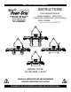
KEEP FOR FUTURE REFERENCE INSTRUCTIONS International Version P.O.
TABLE OF CONTENTS SPECIFICATIONS ............................................................................................................ 3 WARNINGS ..................................................................................................................... 4 OPERATING FEATURES ................................................................................................... 5 ASSEMBLY .............................................................................................................
TESTING SCHEDULE .................................................................................................................. 19 Operational Tests .......................................................................................................................................19 Load Test ..................................................................................................................................................19 MAINTENANCE SCHEDULE ........................................
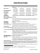
SPECIFICATIONS Description: Designed for use with a crane or other hoisting equipment, MT-FS10TDC lifters employ vacuum to hold a load for lifting, and they provide manual 90° tilt movement for load manipulation.
WARNINGS Powr-Grip is pleased to offer the most reliable vacuum lifters available. Despite the high degree of security provided by this product, certain precautions must be observed to protect the operator and others. Always wear personal protective equipment that is appropriate for the material being handled. Follow trade association guidelines. Always operate the lifter under conditions approved for its design (see INTENDED USE: OPERATING ENVIRONMENT).
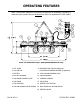
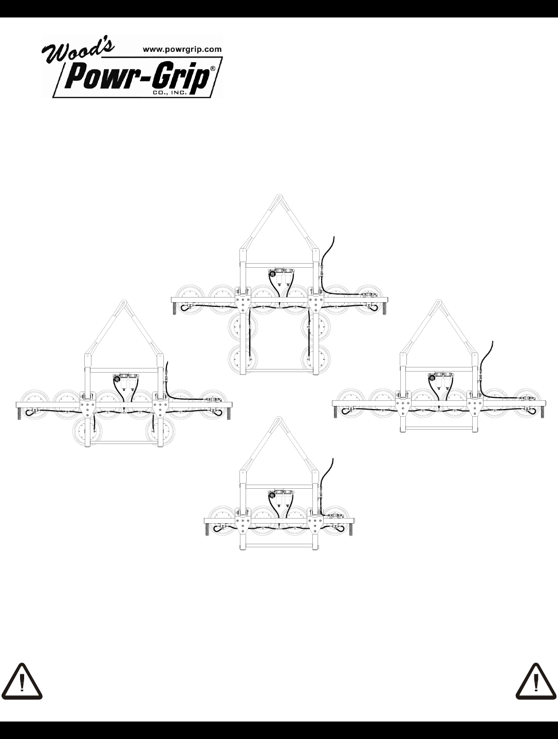
OPERATING FEATURES Note: Components featured in the following instructions for assembling, operating or maintaining the vacuum lifter are underlined on their first appearance in each section. Note: For illustration only―Pad Spread dimensions vary.
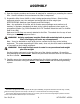
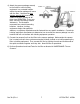
ASSEMBLY 1) Open the shipping container and remove all materials for restraining or protecting the vacuum lifter. Save the container for use whenever the lifter is transported. 2) Suspend the lifter from a forklift or other hoisting equipment as follows: Select hoisting equipment rated to carry the maximum load weight plus the lifter weight (see SPECIFICATIONS: Maximum Load Capacity and Lifter Weight).
4) Attach the vacuum package securely location 1 --> to the forklift or other hoisting equipment in a protected location <-- location 2 where the vacuum package will move with the lifter. Note that the low vacuum warning light must remain visible to the lifter operator at all times (see OPERATION: TO LIFT AND MOVE THE LOAD: Monitoring Vacuum Indicators). The illustration represents two potential mounting locations.
INTENDED USE LOAD CHARACTERISTICS WARNING: This lifter is NOT intended for lifting hazardous materials, such as explosives or radioactive substances. The operator must verify that the lifter is intended to handle each load, in accordance with the following requirements: • The load must not exceed the maximum allowable weight specified under Load Capacity (see SPECIFICATIONS). • The load must be a single piece of nonporous or semiporous material with a flat and relatively smooth contact surface.
OPERATING ENVIRONMENT The operator must determine whether the lifter is intended to be used in each work environment, in accordance with the following restrictions: WARNING: Never use lifter in dangerous environments. • This lifter is not intended for use in any environment that is inherently dangerous to the operator or likely to compromise the lifter's ability to function. Environments containing explosives, caustic chemicals and other dangerous substances must be avoided when using the lifter.
OPERATION BEFORE USING THE LIFTER The operator must determine whether the lifter is capable of performing each intended task, in accordance with the SPECIFICATIONS and INTENDED USE sections of this INSTRUCTIONS manual. In addition, all of the following preparations must be completed prior to lifting any load. Taking Safety Precautions The operator must be trained in all relevant industry and regulatory standards for the operation of the vacuum lifter in its geographical location (eg, ASME B30.
In order to be considered clearly audible, the alarm volume must exceed ambient noise by at least 15 dBA at the operator position.6 Since the Maximum Alarm Volume is 103 dBA, ambient noise must not exceed 88 dBA under any circumstances. Furthermore, if ambient noise measures 88 dBA, the alarm volume must be set to maximum and the operator must remain within 2 ft [60 cm] of the warning buzzer, in order for it to be effective.
TO APPLY THE PADS TO A LOAD Positioning the Lifter on the Load Make certain that the contact surfaces of the load and all vacuum pads are free of any contaminates that could prevent the pads from sealing against the load (see MAINTENANCE: VACUUM PAD MAINTENANCE). The lifter is designed to automatically carry the load in an upright orientation. Center the pad frame from left to right on the load.
Vacuum Level on Optimal Surfaces When the lifter is attached to clean, smooth, nonporous load surfaces, it should be able to maintain a vacuum level in the green range on the vacuum gauge, except when used at high elevations (see SPECIFICATIONS: Operating Elevation). If not, make sure the vacuum switch is adjusted correctly (see MAINTENANCE: VACUUM SWITCH ADJUSTMENT).
Monitoring Vacuum Indicators The low vacuum warning light and the vacuum gauge must remain completely visible to the operator, so that they can be monitored throughout the entire lift. WARNING: Vacuum indicators must be visible to operator throughout entire lift. If the vacuum system experiences leakage while the lifter is attached to the load, the vacuum pump turns on automatically, as required to maintain sufficient vacuum for lifting the maximum load weight.
Controlling the Lifter and Load When vacuum indicators show that the lifter is ready, use the hoisting equipment to raise the lifter and load as needed to clear any obstacles in their path. A load in the flat position automatically tilts toward the upright position when lifted, due to the lifter’s design (see TO TILT to follow). Use the control handles to keep the lifter and load in the desired orientation while they are suspended from the hoisting equipment.
TO RELEASE THE PADS FROM THE LOAD WARNING: Load must be fully supported before releasing vacuum pads. When the load is at rest and fully supported, the vacuum pads can be released either locally (from lifter location) or remotely (from vacuum package location). Releasing the pads locally Move the slide on the pad frame control valve to the “RELEASE” position. After the vacuum pads disengage completely from the load, the lifter can be applied immediately to another load.
AFTER USING THE LIFTER Turn off the remote vacuum package by pushing the vacuum package valve handle inward to the “RELEASE” position, and leave the slide on the pad frame control valve in the “RELEASE” position. CAUTION: Do not set the lifter against any surfaces which could soil or damage the vacuum pads. Use the hoisting equipment to gently lower the lifter onto a stable support; then detach the hoisting equipment hook from the lift slings.
MAINTENANCE WARNING: Always make sure battery is disconnected before servicing lifter. Note: One or more wiring diagrams are provided in the final section of this INSTRUCTIONS manual for reference when servicing the lifter or trouble-shooting a deficiency. INSPECTION SCHEDULE Perform inspections routinely, according to the following frequency schedule: Every-Lift Inspection • Examine the vacuum pads and load surface for contamination or debris (see VACUUM PAD MAINTENANCE to follow).
• Keep a written record of all Periodic Inspections. If any deficiency is detected during the inspection, correct it before using the lifter. If necessary, return the lifter to Powr-Grip or an authorized dealer for repair (see LIMITED WARRANTY). Infrequent Use If a lifter is used less than 1 day in a 2-week period, perform the Periodic Inspection each time before using the lifter.
MAINTENANCE SCHEDULE Unless specified elsewhere in this INSTRUCTIONS manual, the lifter does not require maintenance on a routine basis. Instead, maintenance must be performed whenever a deficiency is indicated by routine inspections or tests. Any maintenance warranted must be performed before resuming normal operation of the lifter. BATTERY TEST The lifter is equipped with a battery gauge to help the operator evaluate whether the battery has adequate energy for lifting.
Identify the input voltage marked on the battery charger, and plug it in to an appropriate power source.14 The power source must be equipped with a ground fault circuit interrupter, in order to reduce the risk of electrical shocks. WARNING: Power source must be equipped with ground fault circuit interrupter. Usually a battery takes no more than 16 hours to charge completely, after which the charger shuts off automatically.
• Filter screen missing from pad face: This screen helps prevent debris from plugging the vacuum hose and the air filter. Replace any missing screen immediately (see REPLACEMENT PARTS LIST). • Nicks, cuts or abrasions in sealing edges: Pad damage can reduce the lifting capacity of the lifter. Replace any damaged pad immediately (see REPLACEMENT PARTS LIST).15 WARNING: Replace vacuum pad if sealing edge has any nicks, cuts or abrasions. • Wear, stiffness or glaze: See Friction Coefficient preceding.
VACUUM TEST Test the vacuum system for leakage routinely, as directed in the preceding INSPECTION and TESTING SCHEDULES. 1) Clean the face of each vacuum pad as previously directed (see VACUUM PAD MAINTENANCE: Cleaning). 2) Apply the lifter to a clean, smooth, nonporous surface. The surface should be flat or possess no more curvature than the lifter is designed for (if any).
AIR FILTER MAINTENANCE − SMALL (for 1 oz [30 ml] bowl size filters) Filter Function and Conditions Requiring Service An air filter prevents solid particles and liquid from contaminating components in the vacuum system. CAUTION: Examine air filter regularly and empty when necessary. Liquid must not contact any portion of the filter element; remove trapped liquid regularly.
AIR FILTER MAINTENANCE − LARGE (for 4.4 oz [130 ml] bowl size filters) Filter Function and Conditions Requiring Service An air filter prevents solid particles and liquid from contaminating components in the vacuum system. CAUTION: Examine air filter regularly and empty when necessary. Liquid must not contact any portion of the filter element; remove trapped liquid regularly.
VACUUM PUMP MAINTENANCE − DYNAFLO DV1032102 WARNING: Before proceeding with any maintenance, disconnect power source. If the vacuum pump takes too long to attain full vacuum, it may require maintenance. Replace the diaphragm, gasket/flap valves or (when preferable) the entire head assembly19 (see REPLACEMENT PARTS LIST), as necessary to obtain acceptable pump performance. CAUTION: Do not over-tighten the head screws, because this may damage the threads in the pump body.
VACUUM PUMP MAINTENANCE − THOMAS 107CDC20 WARNING: Before proceeding with any maintenance, disconnect power source. If the vacuum pump (14) takes too long to attain full vacuum, it may require maintenance. Replace the diaphragm, valve flappers or head gasket as necessary to obtain acceptable pump performance (see REPLACEMENT PARTS LIST). Replacing the Diaphragm 1) Remove the four head screws (1) and remove the head (2).
VACUUM SWITCH ADJUSTMENT Vacuum Switch Function21 A vacuum switch controls the low vacuum warning light and the vacuum pump (see OPERATING FEATURES for location of vacuum switch): The valve handle activates the warning light and the pump, which evacuates the vacuum pads.22 After the lifter attains a vacuum level sufficient for lifting the maximum load weight (hereafter, “minimum lifting level”), the vacuum switch automatically turns off the pump and the warning light.
Adjustment Procedure WARNING: Lifting capacity decreases whenever vacuum switch is adjusted to maintain lower vacuum level. 1) Using a 1/4" open-end wrench (as provided), turn the adjustment screw about 1/6th turn at a time (approximately one flat of the screw head). To maintain a lower vacuum level, turn the screw clockwise (when viewing vacuum switch from end with electrical connectors).
REPLACEMENT PARTS LIST Stock No.
LIMITED WARRANTY Powr-Grip products are carefully constructed, thoroughly inspected at various stages of production, and individually tested. They are warranted to be free from defects in workmanship and materials for a period of one year from the date of purchase. If a problem develops during the warranty period, follow the instructions hereafter to obtain warranty service. If inspection shows that the problem is due to defective workmanship or materials, Powr-Grip will repair the product without charge.
Rev 30.
Rev 30.
Rev 30.