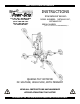
KEEP FOR FUTURE REFERENCE INSTRUCTIONS International Version P.O.
SPECIFICATIONS Description: Designed for use with a crane or other hoisting equipment, MRTA8-DC lifters employ vacuum to hold a load for lifting, and they provide manual 360° rotation and mechanically assisted, manual 90° tilt movements for load manipulation. Model Number: MRTA8HV11DC Vacuum Pads: MRTA811LDC 10" [25 cm] nom. diameter, 11" [28 cm] nom.
WARNINGS Powr-Grip is pleased to offer the most reliable vacuum lifters available. Despite the high degree of security provided by this product, certain precautions must be observed to protect the operator and others. Always wear personal protective equipment that is appropriate for the material being handled. Follow trade association guidelines. Always operate the lifter under conditions approved for its design (see INTENDED USE: OPERATING ENVIRONMENT).
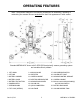
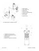
OPERATING FEATURES Note: Components featured in the following instructions for assembling, operating or maintaining the vacuum lifter are underlined on their first appearance in each section. Standard MRTA811LDC shown with 3-SCFM [85 liters/minute] vacuum generating system and movable control pendant.
1 RADIO RECEIVER 2 RADIO TRANSMITTER 3 STROBE LIGHT 4 VACUUM LIFT LIGHT 5 LOW VACUUM WARNING BUZZER 6 ENABLE BUTTON 7 APPLY BUTTON 8 RELEASE BUTTON OPTIONAL REMOTE CONTROL SYSTEM 1 TRANSMISSION INDICATOR LIGHT 2 TRANSMITTER POWER/ENABLE SWITCH 3 RELEASE BUTTONS 4 APPLY BUTTONS 5 EMERGENCY TRANSMITTER DISCONNECT OPTIONAL RADIO TRANSMITTER Rev 2.
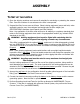
ASSEMBLY TO SET UP THE LIFTER 1) Open the shipping container and remove all materials for restraining or protecting the vacuum lifter. Save the container for use whenever the lifter is transported. 2) Suspend the lifter from a crane as follows: Select hoisting equipment (crane and hoist, when applicable) rated to carry the maximum load weight plus the lifter weight (see SPECIFICATIONS: Maximum Load Capacity and Lifter Weight).
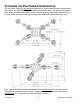
TO CHANGE THE PAD FRAME CONFIGURATION The lifter offers a variety of pad frame configurations to accommodate different load dimensions and weights (see SPECIFICATIONS: Pad Spread and Load Capacity). The following illustrations show several possible configurations. Select a configuration to provide optimal support across the load surface and to minimize load overhang (see OPERATION: BEFORE USING THE LIFTER).
Configurations are created by installing or removing the pad frame’s extension arms, by repositioning or removing the movable pad mounts, and by connecting or disconnecting the vacuum hoses to certain vacuum pads. Always assemble the pad frame in a symmetrical arrangement, to keep the lifter balanced (see illustrations). To support the maximum load weight, all vacuum pads must be installed on the pad frame and all vacuum hoses must be connected to the vacuum pads.
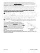
To Reposition (or Remove) Movable Pad Mounts 1) Remove the cotterless hitch pin from one movable pad mount by pulling on the pull ring. 2) Move the pad mount to the desired position on the pad frame and align the holes for the cotterless hitch pin in the pad mount with the corresponding holes in the pad frame. COTTERLESS HITCH PIN 1 PULL RING 2 RETAINING BALL 3) Secure the pad mount by pushing the cotterless hitch pin through the holes until the retaining ball emerges on the far side of the pad mount.
INTENDED USE LOAD CHARACTERISTICS WARNING: This lifter is NOT intended for lifting hazardous materials, such as explosives or radioactive substances. The operator must verify that the lifter is intended to handle each load, in accordance with the following requirements: • The load must not exceed the maximum allowable weight specified under Load Capacity (see SPECIFICATIONS). • The load must be a single piece of nonporous or semiporous material with a flat and relatively smooth contact surface.
Conversely, allowable thickness increases as load weight decreases. In addition, an operator may be able to manually counteract the tendency of unstable loads to tilt out of the upright position, provided that the operator maintains control of the load at all times (see OPERATION: TO LIFT AND MOVE THE LOAD: About the Tilt Linkage and TO TILT THE LOAD). If necessary, contact Wood’s Powr-Grip for help in determining the maximum thickness permitted when handling any specific load.
DISPOSAL OF THE LIFTER After the vacuum lifter has reached the end of its service life, you must dispose of the lifter in compliance with all local codes and regulatory standards that are relevant for the geographical region. Note: This lifter is equipped with a battery, which may be subject to special disposal regulations. Rev 2.
OPERATION BEFORE USING THE LIFTER The operator must determine whether the lifter is capable of performing each intended task, in accordance with the SPECIFICATIONS and INTENDED USE sections of this INSTRUCTIONS manual. In addition, all of the following preparations must be completed prior to lifting any load. Taking Safety Precautions The operator must be trained in all relevant industry and regulatory standards for the operation of the vacuum lifter in its geographical location (eg, ASME B30.
Preparing to Use the Optional Remote Control System If the lifter is equipped with a Remote Control System, the operator can engage the lifter's apply and release functions at distances up to 250' [76 m], provided there is a direct and clear view of the lifter and its status indicators from the operator location (see MAINTENANCE: REMOTE CONTROL SYSTEM TEST). When lifting a load from a remote location, the operator must monitor the lifter at all times to make sure that it is functioning as intended.
Note: While the transmitter is activated, the transmission indicator light will flash green when any button on the transmitter is pressed; otherwise, it will flash red (see BEFORE USING THE LIFTER: Preparing to Use the Optional Remote Control System preceding). Positioning the Lifter on the Load Make certain that the contact surfaces of the load and all vacuum pads are free of any contaminates that could prevent the pads from sealing against the load (see MAINTENANCE: VACUUM PAD MAINTENANCE).
Reading the Vacuum Gauge The vacuum gauge indicates the current vacuum level in the lifter’s vacuum system. The green range indicates vacuum levels sufficient for lifting the maximum load weight, whereas the red range indicates vacuum levels that are not sufficient for lifting the maximum load weight. The gauge needle should show a sudden surge in vacuum as the vacuum pads seal against the load.
TO LIFT AND MOVE THE LOAD About the Tilt Linkage WARNING: Make sure load is positioned correctly on lifter; unbalanced loads may tilt unexpectedly. The lifter’s tilt linkage is designed to automatically hold a balanced load in either the upright or the flat position. However, an unbalanced load may tilt unexpectedly from the flat position to the upright position or vice versa, when lifted. This could result in load damage or injury to anyone positioned in the tilt path of the load.
Load Capacity and the Lift Light A lifter’s Load Capacity is rated at a vacuum level of 16" Hg [-54 kPa] (see SPECIFICATIONS). After the lifter has attained this level, the vacuum pumps turn off automatically, to conserve battery energy. At the same time, the green vacuum lift light turns on, to indicate that the lifter is ready to lift the maximum load weight. WARNING: Never attempt to lift load unless green lift light is illuminated.
TEST). If a power failure occurs, keep all personnel clear of the suspended load until it can safely be placed on the ground or a stable support. Correct any deficiency before resuming normal operation of the lifter. TO ROTATE THE LOAD EDGEWISE WARNING: Make sure load is positioned correctly on lifter (see TO APPLY); unbalanced loads may rotate unexpectedly when latch is disengaged. Remember that the load is longer in its diagonal dimensions than in its side dimensions.
ABOUT THE OPTIONAL ENABLE SWITCH AND STROBE LIGHT If the lifter is equipped with a Remote Control System, there are 2 enable switches: a rotary switch on the radio transmitter, as well as a push-button switch on the lifter (see OPERATING FEATURES). To actuate the enable switch on the lifter, simply press the enable button. To actuate the enable switch on the optional radio transmitter, rotate the transmitter power/enable switch beyond the “ON” position to the “START” position.
AFTER USING THE LIFTER Leave the apply/release switch in the neutral position and place the power switch in the OFF position ( ). The blue indicator light shuts off when the operator powers down the lifter. If the lifter is equipped with a Remote Control System, also turn off the radio transmitter. CAUTION: Do not set the lifter against any surfaces which could soil or damage the vacuum pads.
MAINTENANCE WARNING: Always make sure battery is disconnected before servicing lifter. INSPECTION SCHEDULE Perform inspections routinely, according to the following frequency schedule: Every-Lift Inspection • Examine the vacuum pads and load surface for contamination or debris (see VACUUM PAD MAINTENANCE to follow). • Examine the vacuum pads, controls and indicators for visual damage (see VACUUM PAD MAINTENANCE to follow). • Test the battery for adequate charge (see BATTERY TEST to follow).
• Keep a written record of all Periodic Inspections. If any deficiency is detected during the inspection, correct it before using the lifter. If necessary, return the lifter to Wood’s Powr-Grip or an authorized dealer for repair (see LIMITED WARRANTY). Infrequent Use If a lifter is used less than 1 day in a 2-week period, perform the Periodic Inspection each time before using the lifter.
MAINTENANCE SCHEDULE Unless specified elsewhere in this INSTRUCTIONS manual, the lifter does not require maintenance on a routine basis. Instead, maintenance must be performed whenever a deficiency is indicated by routine inspections or tests. Any maintenance warranted must be performed before resuming normal operation of the lifter. BATTERY TEST The lifter is equipped with a battery gauge to help the operator evaluate whether the battery has adequate energy for lifting.
BATTERY RECHARGE CAUTION: Charge battery only while lifter’s power switch is in the OFF ( ) position. Operating the lifter when the battery charger is connected to an AC power source could result in permanent damage to the charger. Only use a battery charger supplied by or approved by Wood's Powr-Grip; other chargers may reduce battery life. Charge the battery as soon as possible after any extended use of the lifter, or whenever the battery gauge indicates diminished energy (see BATTERY TEST preceding).
VACUUM PAD MAINTENANCE Friction Coefficient The friction coefficient represents the lifter's ability to resist load slippage when the load is oriented in any position except horizontal. If the contact surfaces of either the load or the vacuum pads are not clean, dry and in good condition, slippage is more likely to occur. The Load Capacity of most Powr-Grip lifters is based on a friction coefficient of 1 (only Flat Lifters are exempt from this requirement).
WARNING: Never use unauthorized rubber cleaners or conditioners to clean vacuum pad. To prevent liquid from contaminating the vacuum system during cleaning, cover the suction hole in the recess for the filter screen or make sure the pad faces downward. Use a clean sponge or lint-free cloth to apply an authorized cleanser and wipe the pad face clean. A toothbrush (or similar brush with bristles that do not harm rubber) may be used to remove contaminates clinging to sealing edges.
REMOTE CONTROL SYSTEM TEST If the lifter is equipped with a Remote Control System, perform this test in the environment where the lifter is normally employed. Use the radio transmitter to activate each of the remote functions.22 Vary the location and distance of the transmitter in relation to the lifter, to ensure that transmissions are effective in a variety of circumstances. This may require assistance from someone near the lifter, to verify that functions are being performed as intended.
AIR FILTER MAINTENANCE (for 4.4 oz [130 ml] bowl size filters) Filter Function and Conditions Requiring Service An air filter prevents solid particles and liquid from contaminating components in the vacuum system. CAUTION: Examine air filter regularly and empty when necessary. Liquid must not contact any portion of the filter element; remove trapped liquid regularly. Replace the element if it has an overall dirty appearance, or if there is a noticeable increase in the time required to attain full vacuum.
VACUUM PUMP MAINTENANCE (for Thomas pump no. 2907CDC22/12) WARNING: Before proceeding with any maintenance, disconnect power source. If the vacuum pump takes too long to attain full vacuum, it may require maintenance. Replace the diaphragms, valve flappers or head gaskets as necessary to obtain acceptable pump performance (see REPLACEMENT PARTS LIST). Perform the following procedures on both heads of the pump. Replacing a Diaphragm (1) 1) Remove the six head screws (14) and remove the head (13).
VACUUM PUMP MAINTENANCE (for Dynaflo pump no. DV1032102) WARNING: Before proceeding with any maintenance, disconnect power source. If the vacuum pump takes too long to attain full vacuum, it may require maintenance. Replace the diaphragm, gasket/flap valves or (when preferable) the entire head assembly24 (see REPLACEMENT PARTS LIST), as necessary to obtain acceptable pump performance. CAUTION: Do not over-tighten the head screws, because this may damage the threads in the pump body.
VACUUM SWITCH ADJUSTMENT Vacuum Switch Function25 A vacuum switch controls the vacuum pump and the vacuum lift light (see OPERATING FEATURES for location of vacuum switch). When the power switch located on the lifter is in the ON position ( ), activating the apply function engages the vacuum pump, which evacuates the vacuum pads.
maintain a higher vacuum level.27 Otherwise, the lifter would not maintain sufficient vacuum to lift the maximum load weight. Adjustment Procedure WARNING: Load capacity decreases whenever vacuum switch is adjusted to maintain lower vacuum level. 1) Using a 1/4" open-end wrench (as provided), turn the adjustment screw about 1/6th turn at a time (approximately one flat of the screw head).
REPLACEMENT PARTS LIST Stock No.
LIMITED WARRANTY Powr-Grip products are carefully constructed, thoroughly inspected at various stages of production, and individually tested. They are warranted to be free from defects in workmanship and materials for a period of one year from the date of purchase. If a problem develops during the warranty period, follow the instructions hereafter to obtain warranty service. If inspection shows that the problem is due to defective workmanship or materials, Powr-Grip will repair the product without charge.
LOW VACUUM WARNING BUZZER SPECIFICATIONS Maximum Alarm Volume: 103 dBa at 2' [60 cm] Function: While the lifter is powered up, an audible alarm warns the operator whenever vacuum is not sufficient for lifting the maximum load weight. OPERATION Before Using the Lifter WARNING: Make sure alarm is clearly audible over ambient noise at operator position. The volume of the alarm may be adjusted by rotating the shutter of the low vacuum warning buzzer.
If the vacuum system experiences leakage while the lifter is attached to the load, the vacuum pump turns on automatically, as required to maintain sufficient vacuum. The alarm also sounds while the pump is running, to signal the reduction in vacuum to the operator. If the alarm sounds while you are lifting a load, make sure the vacuum gauge shows a vacuum level of 16" Hg [-54 kPa] or higher. If not, immediately move away and stay clear of the load until it can be lowered to the ground or a stable support.