KEEP FOR FUTURE REFERENCE INSTRUCTIONS International Version P.O.
TABLE OF CONTENTS SPECIFICATIONS ............................................................................................................ 3 WARNINGS ..................................................................................................................... 4 OPERATING FEATURES ................................................................................................... 5 ASSEMBLY .............................................................................................................
MAINTENANCE ............................................................................................................. 21 INSPECTION SCHEDULE ............................................................................................................. 21 Every-Lift Inspection ..................................................................................................................................21 Frequent Inspection ...............................................................................
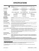
SPECIFICATIONS Description: Model Number: Vacuum Pads:1 Pad Spread: Minimum: Maximum: Load Capacity: Per-Pad: Maximum w/4 pads: Maximum w/6 pads: Lifter Weight: Designed for use with a crane or other hoisting equipment, MRTALPCH6-DC lifters employ vacuum to hold a load for lifting, and they provide manual 180° rotation and manual 90° tilt movements for load manipulation.
WARNINGS Powr-Grip is pleased to offer the most reliable vacuum lifters available. Despite the high degree of security provided by this product, certain precautions must be observed to protect the operator and others. Always wear personal protective equipment that is appropriate for the material being handled. Follow trade association guidelines. Always operate the lifter under conditions approved for its design (see INTENDED USE: OPERATING ENVIRONMENT).
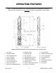
OPERATING FEATURES Note: Components featured in the following instructions for assembling, operating or maintaining the vacuum lifter are underlined on their first appearance in each section. Standard MRTALPCH611LDC shown with Remote Control System option.
1 TRANSMISSION INDICATOR LIGHT 2 TRANSMITTER POWER/ENABLE BUTTON 3 RELEASE BUTTONS 4 APPLY BUTTONS 5 EMERGENCY TRANSMITTER DISCONNECT OPTIONAL RADIO TRANSMITTER Rev 8.
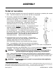
ASSEMBLY TO SET UP THE LIFTER 1) Open the shipping container and remove all materials for restraining or protecting the vacuum lifter. Save the container for use whenever the lifter is transported. 2) If necessary, assemble the lifter's lift bar as follows: One segment of the lift bar can be removed, to reduce overall lifter dimensions for shipping. If so, orient the removable segment (1) as shown in the illustration, and slide it over the other segment until the bolt holes align.
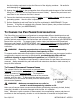
Use the hoisting equipment to raise the lifter out of the shipping container. Be careful to avoid damaging any vacuum pads. 5) Arrange the pad frame in the configuration that will provide optimal support of the load while lifting (see TO CHANGE THE PAD FRAME CONFIGURATION to follow). Remove the pad covers and save them for use whenever the lifter is stored. 6) Connect the electrical connectors uniting the battery to the battery charger and the vacuum generating system. Now the lifter is operational.
To Install/Remove Pad Frame Extensions 1) Set the lifter with the vacuum pads facing downward on a clean, smooth, flat surface. 2) Insert the tabs extending from one pad frame extension between the rails of the pad frame. If the tabs do not fit between the rails, you may loosen the bolts that connect the tabs to the extension. Make sure that the vacuum pads on the extension and on the pad frame are contacting the same surface, to ensure that all the pads are aligned in the same plane.
INTENDED USE LOAD CHARACTERISTICS WARNING: This lifter is NOT intended for lifting hazardous materials, such as explosives or radioactive substances. The operator must verify that the lifter is intended to handle each load, in accordance with the following requirements: • The load must not exceed the maximum allowable weight specified under Load Capacity (see SPECIFICATIONS). • The load must be a single piece of nonporous or semiporous material with a flat and relatively smooth contact surface.
Conversely, allowable thickness increases as load weight decreases. In addition, an operator may be able to manually counteract the tendency of unstable loads to tilt out of the upright position, provided that the operator maintains control of the load at all times (see OPERATION: TO LIFT AND MOVE THE LOAD: About the Tilt Linkage and TO TILT THE LOAD). If necessary, contact Wood’s Powr-Grip for help in determining the maximum thickness permitted when handling any specific load.
OPERATION BEFORE USING THE LIFTER The operator must determine whether the lifter is capable of performing each intended task, in accordance with the SPECIFICATIONS and INTENDED USE sections of this INSTRUCTIONS manual. In addition, all of the following preparations must be completed prior to lifting any load. Taking Safety Precautions The operator must be trained in all relevant industry and regulatory standards for the operation of the vacuum lifter in its geographical location (eg, ASME B30.
CAUTION: Examine each air filter regularly, and empty when necessary. Two air filters help protect the vacuum generating system from contaminants. However, the lifter is not intended for use on wet load surfaces because the filters would not prevent liquid from entering the vacuum system. The operator must examine each filter regularly and remove any liquid or other contaminants found inside (see MAINTENANCE: AIR FILTER MAINTENANCE).
TO APPLY THE PADS TO A LOAD Positioning the Lifter on the Load Make certain that the contact surfaces of the load and all vacuum pads are free of any contaminates that could prevent the pads from sealing against the load (see MAINTENANCE: VACUUM PAD MAINTENANCE). Center the lifter’s pad frame to within 2" [5 cm] of the load center, since off-center loading can cause the load to rotate or tilt unexpectedly (see TO ROTATE THE LOAD EDGEWISE or TO TILT THE LOAD to follow), and it may also damage the lifter.
WARNING: Keep apply function activated throughout lift. Note: If a vacuum pad has been lying against a hard object (as during shipping), it may be slightly distorted. Although initially it may be difficult to apply the pad to a load, this condition should correct itself with continued use. Reading the Vacuum Gauges The lifter is equipped with 2 vacuum gauges, which indicate the current vacuum level in each circuit of the lifter’s vacuum system.
TO LIFT AND MOVE THE LOAD Positioning the Lift Bar WARNING: Lift bar must be oriented vertically to lift load. Never lift the load from a flat position with the lift bar latched parallel to the load. Always disengage the tilt latch (see TO TILT THE LOAD to follow) and raise the lift bar to a vertical orientation before attempting to lift. Interpreting the Warning Buzzer and Lift Light A lifter's Load Capacity is rated at a vacuum level of 16" Hg [-54 kPa] (see SPECIFICATIONS).
Monitoring the Low Vacuum Warning Buzzer Using the low vacuum warning buzzer requires minimal interaction from the operator. The warning buzzer sounds an alarm until the lifter attains sufficient vacuum to lift the maximum load weight (see SPECIFICATIONS: Load Capacity). After the lifter has attained this vacuum level, the alarm stops sounding, to indicate that the lifter is ready to lift the load. WARNING: Never attempt to lift load while alarm is sounding.
TO ROTATE THE LOAD EDGEWISE WARNING: Never disengage both the rotation latch and the tilt latch at the same time. This lifter is not designed for rotation and tilt functions to be used at the same time. Disengaging the rotation and tilt latches simultaneously could cause uncontrolled and unpredictable load movement, potentially resulting in load damage or injury to the operator. CAUTION: Rotation function only works when pad frame is latched in vertical orientation.
TO TILT THE LOAD WARNING: Never disengage both the rotation latch and the tilt latch at the same time. This lifter is not designed for rotation and tilt functions to be used at the same time. Disengaging the rotation and tilt latches simultaneously could cause uncontrolled and unpredictable load movement, potentially resulting in load damage or injury to the operator. CAUTION: Tilt function only works when pad frame is latched in center position of rotation range.
The operator must never attempt to move the lifter or load until the vacuum pads are completely disengaged, as this could cause an unexpected load release and potential injury to the operator or others. If the vacuum pads do not disengage completely on the first attempt, repeat the release process. If the load cannot be successfully released for any reason, reapply the vacuum pads to the load as previously directed (see TO APPLY THE PADS TO A LOAD preceding) prior to moving the lifter or load.
MAINTENANCE WARNING: Always make sure battery is disconnected before servicing lifter. Note: One or more wiring diagrams are provided in the final section of this INSTRUCTIONS manual for reference when servicing the lifter or trouble-shooting a deficiency. INSPECTION SCHEDULE Perform inspections routinely, according to the following frequency schedule: Every-Lift Inspection • Examine the vacuum pads and load surface for contamination or debris (see VACUUM PAD MAINTENANCE to follow).
CAUTION: Be sure to use appropriate cleaning methods for each type of electrical component, as specified by codes and standards. Improper cleaning can damage components. • Keep a written record of all Periodic Inspections. If any deficiency is detected during the inspection, correct it before using the lifter. If necessary, return the lifter to Wood’s Powr-Grip or an authorized dealer for repair (see LIMITED WARRANTY).
MAINTENANCE SCHEDULE Unless specified elsewhere in this INSTRUCTIONS manual, the lifter does not require maintenance on a routine basis. Instead, maintenance must be performed whenever a deficiency is indicated by routine inspections or tests. Any maintenance warranted must be performed before resuming normal operation of the lifter. BATTERY TEST The lifter is equipped with a battery gauge to help the operator evaluate whether the battery has adequate energy for lifting.
Identify the input voltage marked on the battery charger, and plug it in to an appropriate power source.16 The power source must be equipped with a ground fault circuit interrupter, in order to reduce the risk of electrical shocks. WARNING: Power source must be equipped with ground fault circuit interrupter. Usually a battery takes no more than 16 hours to charge completely, after which the charger shuts off automatically.
Inspection Inspect each vacuum pad for the following deficiencies routinely, as directed in the preceding INSPECTION and TESTING SCHEDULES. Correct any deficiency before using the lifter. • Contaminates on the pad face or sealing edges: Soil build-up can prevent pads from sealing adequately or reduce the friction coefficient (see discussion preceding). Follow the directions to clean pads as necessary (see discussion to follow).
VACUUM TEST Test the vacuum system for leakage routinely, as directed in the preceding INSPECTION and TESTING SCHEDULES. 1) Clean the face of each vacuum pad as previously directed (see VACUUM PAD MAINTENANCE: Cleaning). 2) Apply the lifter to a clean, smooth, nonporous surface. The surface should be flat or possess no more curvature than the lifter is designed for (if any).
AIR FILTER MAINTENANCE (for in-line filters) Filter Function and Conditions Requiring Service This air filter prevents solid particles from contaminating components in the vacuum system. CAUTION: Examine air filter regularly and empty when necessary. Open each filter regularly to determine whether liquid or other contaminants are trapped inside. Remove any liquid or contaminants found.
VACUUM PUMP MAINTENANCE − DYNAFLO DV1032102 WARNING: Before proceeding with any maintenance, disconnect power source. If the vacuum pump takes too long to attain full vacuum, it may require maintenance. Replace the diaphragm, gasket/flap valves or (when preferable) the entire head assembly21 (see REPLACEMENT PARTS LIST), as necessary to obtain acceptable pump performance. CAUTION: Do not over-tighten the head screws, because this may damage the threads in the pump body.
VACUUM PUMP MAINTENANCE − THOMAS 107CDC20 WARNING: Before proceeding with any maintenance, disconnect power source. If the vacuum pump (14) takes too long to attain full vacuum, it may require maintenance. Replace the diaphragm, valve flappers or head gasket as necessary to obtain acceptable pump performance (see REPLACEMENT PARTS LIST). Replacing the Diaphragm 1) Remove the four head screws (1) and remove the head (2).
VACUUM SWITCH ADJUSTMENT Vacuum Switch Function This vacuum lifter is equipped with a vacuum switch, which controls the low vacuum warning buzzer, vacuum lift light and vacuum pump (see OPERATING FEATURES for location of vacuum switch): The power switch activates the warning buzzer and the pump, which evacuates the vacuum pads.
Adjustment Procedure WARNING: Lifting capacity decreases whenever vacuum switch is adjusted to maintain lower vacuum level. 1) Locate the access hole in the enclosure that contains the vacuum switch (see OPERATING FEATURES), and remove the plug from the hole. Using a flat-blade screwdriver, turn the adjustment screw on the vacuum switch about 1/6th turn at a time. To maintain a lower vacuum level, turn the screw clockwise. To maintain a higher vacuum level, turn the screw counterclockwise.
REPLACEMENT PARTS LIST Stock No.
LIMITED WARRANTY Powr-Grip products are carefully constructed, thoroughly inspected at various stages of production, and individually tested. They are warranted to be free from defects in workmanship and materials for a period of one year from the date of purchase. If a problem develops during the warranty period, follow the instructions hereafter to obtain warranty service. If inspection shows that the problem is due to defective workmanship or materials, Powr-Grip will repair the product without charge.
Rev 8.
Rev 8.
Rev 8.