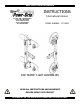
KEEP FOR FUTURE REFERENCE INSTRUCTIONS P.O.
SPECIFICATIONS Option Model Number: CF13CEO Description: When installed, Pad Frame T-Arm Assemblies enable a vacuum lifter to handle cladding and textured materials with various profiles and dimensions.
WARNINGS Powr-Grip is pleased to offer the most reliable materials handling products available. Despite the high degree of security provided by the Pad Frame T-Arm Assemblies, certain precautions must be observed to protect the user and others. Always wear personal protective equipment that is appropriate for the material being handled. Follow trade association guidelines. Always use the T-arm assemblies under conditions approved for the design of the vacuum lifter (see lifter's instruction manual).
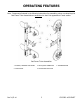
OPERATING FEATURES Note: Components featured in the following instructions for assembling, using or maintaining the Pad Frame T-Arm Assemblies are underlined on their first appearance in each section. Pad Frame T-Arm Assemblies 1 SLIDING / MOVABLE PAD MOUNT 3 MALE QUICK CONNECTOR 2 VACUUM PAD 4 COTTERLESS HITCH PIN Rev 2.
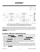
ASSEMBLY MRTA-DC shown with Pad Frame T-Arm Assemblies and VPFS625 pads. Note: For illustration only―Pad Spread dimensions may vary. Assemble the vacuum lifter as directed in the lifter's instruction manual. However, instead of the standard extension arms and vacuum pads, install the 2 Pad Frame T-Arm Assemblies with all 4 vacuum pads and connect all the vacuum hoses, as directed in the following sections. Note: Use only 2 pads on each T-arm assembly.
5) Repeat steps #1-4 to install the second T-arm assembly, as shown in the preceding illustration. 6) To remove T-arm assemblies, reverse this procedure. Store removed T-arm assemblies in a clean, dry location to protect them from environmental exposure. Set the vacuum pads facing upward, because prolonged pressure against the sealing rings may cause them to become distorted.
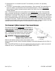
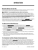
OPERATION BEFORE USING THE LIFTER Consult the lifter's instruction manual to determine all safety precautions, inspections, tests and other preparations which must be completed prior to using the vacuum lifter. WARNING: T-arm assemblies may reduce lifter's Load Capacity.
Note: Depending on the position of pad mounts, the pad frame may extend beyond the edges of smaller loads. When moving such loads, be careful to avoid any obstacles to the pad frame, as well as to the load. MAINTENANCE When performing inspections and tests as directed in the lifter's instruction manual, be sure to include all parts of each Pad Frame T-Arm Assembly whenever applicable. When necessary, replace the sealing ring inserts for vacuum pads as directed below.
LIMITED WARRANTY Powr-Grip products are carefully constructed, thoroughly inspected at various stages of production, and individually tested. They are warranted to be free from defects in workmanship and materials for a period of one year from the date of purchase. If a problem develops during the warranty period, follow the instructions hereafter to obtain warranty service. If inspection shows that the problem is due to defective workmanship or materials, Powr-Grip will repair the product without charge.