
User Manual

Rev 9.0/6-12 12 MRTA8-DC: #35075
TO APPLY THE PADS TO A LOAD
Powering up the Lifter
Make sure the lever on the vacuum control valve is in the center position (see TO RELEASE THE
PADS FROM THE LOAD: About Energy Conservation Mode to follow). Place the power switch in the
"ON" position (blue indicator light remains illuminated while power is engaged).
6
The power
switch must remain in the "ON" position while operating the lifter.
WARNING: Never turn power off while operating lifter.
Placing the power switch in the "OFF" position during lifter operation could result in the release of
the load and possible injury to the operator (see TO LIFT AND MOVE THE LOAD: In Case of Power
Failure to follow).
Positioning the Lifter on the Load
Make certain that the contact surfaces of the load and all vacuum pads are free of any
contaminates that could prevent the pads from sealing against the load (see MAINTENANCE:
VACUUM PAD MAINTENANCE).
Center the lifter’s pad frame to within 2" [5 cm] of the load center, since off-center loading can
cause the load to tilt or rotate unexpectedly (see TO LIFT AND MOVE THE LOAD: About the Tilt
Linkage and TO ROTATE THE LOAD EDGEWISE to follow), and it may also damage the lifter.
7
Make
sure that all vacuum pads will fit entirely on the load’s contact surface (see SPECIFICATIONS:
Pad Spread) and that they will be loaded evenly while lifting (see SPECIFICATIONS: Per-Pad Load
Capacity). Then position the lifter on the load so that all pads are touching the contact surface.
Sealing the Pads against the Load
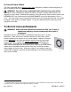
Move the lever on the vacuum control valve to the “APPLY” position: Pull outward on the lever's
knob, move the lever all the way to the
right
and release it. This position opens the lifter’s
vacuum lines to the airflow created by the vacuum pump, causing air to be drawn immediately at
the vacuum pads.
8
Apply the lifter to the load until all pads seal against it.
WARNING: Keep valve lever in “APPLY” position throughout lift.
The valve lever must remain in the “APPLY” position throughout the entire lift. Any interruption
of the vacuum flow during lifter operation could result in the release of the load and possible
injury to the operator.
Note: If a vacuum pad has been lying against a hard object (as during shipping), it may be
slightly distorted. Although initially it may be difficult to apply the pad to a load, this condition
should correct itself with continued use.
6
After the power switch is placed in the "ON" position, the low vacuum warning light and the vacuum pump turn on until the
lifter attains full vacuum. Since the lifter is operating in energy conservation mode at this stage, the pump and warning light may
subsequently turn off. However, this does
not
indicate that the lifter is ready to lift a load.
7
The lifter is designed to handle the maximum load weight (see SPECIFICATIONS: Maximum Load Capacity) when the load’s
center of gravity is positioned within 2" [5 cm] of the pad frame’s center point. Occasional loading deviations are permissible,
provided that the operator can maintain control of the load at all times and that the load weight is low enough to avoid damaging
the lifter.
8
To conserve battery energy and reduce the time required to apply the pads to a load, do not place the valve lever in the
“APPLY” position unless the vacuum pads are contacting the load.