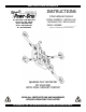
KEEP FOR FUTURE REFERENCE INSTRUCTIONS International Version P.O.
TABLE OF CONTENTS SPECIFICATIONS ............................................................................................................ 3 WARNINGS ..................................................................................................................... 4 OPERATING FEATURES ................................................................................................... 5 ASSEMBLY .............................................................................................................
MAINTENANCE ............................................................................................................. 20 INSPECTION SCHEDULE ............................................................................................................. 20 Every-Lift Inspection ..................................................................................................................................20 Frequent Inspection ...............................................................................
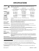
SPECIFICATIONS Description: Designed for use with a crane or other hoisting equipment, the MRTA6-DC lifters employ vacuum to hold a load for lifting, and they provide manual 360° rotation and mechanically assisted, manual 90° tilt movements for load manipulation. Model Number: 1 Vacuum Pads: MRTA611LDC MRTA6HV11FDC MRTA610DCO (Six of standard rubber, spring-mounted with 1/4" [7 mm] travel and #60 filter screen) 11" [28 cm] nominal diameter, 10" [25 cm] nom. diameter, 10" [25 cm] nom.
WARNINGS Powr-Grip is pleased to offer the most reliable vacuum lifters available. Despite the high degree of security provided by this product, certain precautions must be observed to protect the operator and others. Always wear personal protective equipment that is appropriate for the material being handled. Follow trade association guidelines. Always operate the lifter under conditions approved for its design (see INTENDED USE: OPERATING ENVIRONMENT).
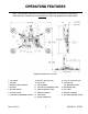
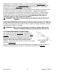
OPERATING FEATURES Note: Components featured in the following instructions for assembling, operating or maintaining the vacuum lifter are underlined on their first appearance in each section. Standard MRTA611LDC shown.
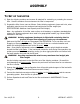
ASSEMBLY TO SET UP THE LIFTER 1) Open the shipping container and remove all materials for restraining or protecting the vacuum lifter. Save the container for use whenever the lifter is transported. 2) Suspend the lifter from a crane as follows: Select hoisting equipment (crane and hoist, when applicable) rated to carry the maximum load weight plus the lifter weight (see SPECIFICATIONS: Maximum Load Capacity and Lifter Weight).
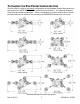
TO CHANGE THE PAD FRAME CONFIGURATION The lifter offers a variety of pad frame configurations to accommodate different load dimensions and weights (see SPECIFICATIONS: Pad Spread and Load Capacity). The following illustration shows several possible configurations. Select a configuration to provide optimal support across the load surface and to minimize load overhang (see OPERATION: BEFORE USING THE LIFTER). Standard MRTA611LDC pad frame shown. Rev 14.
Configurations are created by installing or removing the pad frame’s extension arms, by repositioning or removing the movable pad mounts, and by connecting or disconnecting the vacuum hoses to certain vacuum pads. Always assemble the pad frame in a symmetrical arrangement, to keep the lifter balanced (see illustration). To support the maximum load weight, all vacuum pads must be installed on the pad frame and all vacuum hoses must be connected to the vacuum pads.
To Reposition (or Remove) Movable Pad Mounts 1) Remove the cotterless hitch pin from one movable pad mount by pulling on the pull ring. 2) Move the pad mount to the desired position on the pad frame and align the holes for the cotterless hitch pin in the pad mount with the corresponding holes in the pad frame. COTTERLESS HITCH PIN 1 PULL RING 2 RETAINING BALL 3) Secure the pad mount by pushing the cotterless hitch pin through the holes until the retaining ball emerges on the far side of the pad mount.
INTENDED USE LOAD CHARACTERISTICS WARNING: This lifter is NOT intended for lifting hazardous materials, such as explosives or radioactive substances. The operator must verify that the lifter is intended to handle each load, in accordance with the following requirements: • The load must not exceed the maximum allowable weight specified under Load Capacity (see SPECIFICATIONS). • The load must be a single piece of nonporous or semiporous material with a flat and relatively smooth contact surface.
Conversely, allowable thickness increases as load weight decreases. In addition, an operator may be able to manually counteract the tendency of unstable loads to tilt out of the upright position, provided that the operator maintains control of the load at all times (see OPERATION: TO LIFT AND MOVE THE LOAD: About the Tilt Linkage and TO TILT THE LOAD). If necessary, contact Wood’s Powr-Grip for help in determining the maximum thickness permitted when handling any specific load.
OPERATION BEFORE USING THE LIFTER The operator must determine whether the lifter is capable of performing each intended task, in accordance with the SPECIFICATIONS and INTENDED USE sections of this INSTRUCTIONS manual. In addition, all of the following preparations must be completed prior to lifting any load. Taking Safety Precautions The operator must be trained in all relevant industry and regulatory standards for the operation of the vacuum lifter in its geographical location (eg, ASME B30.
CAUTION: Examine each air filter regularly, and empty when necessary. Two air filters help protect the vacuum generating system from contaminants. However, the lifter is not intended for use on wet load surfaces because the filters would not prevent liquid from entering the vacuum system. The operator must examine each filter bowl regularly and remove any liquid or other contaminants found inside (see MAINTENANCE: AIR FILTER MAINTENANCE).
Note: If a vacuum pad has been lying against a hard object (as during shipping), it may be slightly distorted. Although initially it may be difficult to apply the pad to a load, this condition should correct itself with continued use. Reading the Vacuum Gauges The lifter is equipped with 2 vacuum gauges, which indicate the current vacuum level in each circuit of the lifter’s vacuum system.
TO LIFT AND MOVE THE LOAD About the Tilt Linkage WARNING: Make sure load is positioned correctly on lifter; unbalanced loads may tilt unexpectedly. The lifter’s tilt linkage is designed to automatically hold a balanced load in either the upright or the flat position. However, an unbalanced load may tilt unexpectedly from the flat position to the upright position, or vice versa, when lifted. This could result in load damage or injury to anyone positioned in the tilt path of the load.
Monitoring Vacuum Indicators The low vacuum warning light and both vacuum gauges must remain completely visible to the operator, so that they can be monitored throughout the entire lift. WARNING: Vacuum indicators must be visible to operator throughout entire lift. If the vacuum system experiences leakage while the lifter is attached to the load, the vacuum pump turns on automatically, as required to maintain sufficient vacuum for lifting the maximum load weight.
Controlling the Lifter and Load When the vacuum indicators show that the lifter is ready, use the hoisting equipment to raise the lifter and load as needed to clear any obstacles in their path. Use the control handle to keep the lifter and load in the desired orientation while they are suspended from the crane. Once sufficient clearance is established, the load can be rotated or tilted as desired (see TO ROTATE THE LOAD EDGEWISE or TO TILT THE LOAD to follow).
TO TILT THE LOAD WARNING: Always keep hands and fingers away from bars of tilt linkage. Remember that the load requires more vertical space when tilted to the upright position, as well as more horizontal space when tilted to the flat position. Make sure there is sufficient clearance for the load to tilt without contacting the operator or any nearby objects. Also make sure the tilt locks are disengaged prior to tilting the load (see TO LIFT AND MOVE THE LOAD: Engaging or Disengaging Tilt Locks preceding).
AFTER USING THE LIFTER Leave the valve handle in the “RELEASE” position (power off). CAUTION: Do not set the lifter against any surfaces which could soil or damage the vacuum pads. Use the hoisting equipment to gently lower the lifter onto a stable support; then detach the hoisting equipment hook from the lift spool.
MAINTENANCE WARNING: Always make sure battery is disconnected before servicing lifter. Note: One or more wiring diagrams are provided in the final section of this INSTRUCTIONS manual for reference when servicing the lifter or trouble-shooting a deficiency. INSPECTION SCHEDULE Perform inspections routinely, according to the following frequency schedule: Every-Lift Inspection • Examine the vacuum pads and load surface for contamination or debris (see VACUUM PAD MAINTENANCE to follow).
• Keep a written record of all Periodic Inspections. If any deficiency is detected during the inspection, correct it before using the lifter. If necessary, return the lifter to Powr-Grip or an authorized dealer for repair (see LIMITED WARRANTY). Infrequent Use If a lifter is used less than 1 day in a 2-week period, perform the Periodic Inspection each time before using the lifter.
MAINTENANCE SCHEDULE Unless specified elsewhere in this INSTRUCTIONS manual, the lifter does not require maintenance on a routine basis. Instead, maintenance must be performed whenever a deficiency is indicated by routine inspections or tests. Any maintenance warranted must be performed before resuming normal operation of the lifter. BATTERY TEST The lifter is equipped with a battery gauge to help the operator evaluate whether the battery has adequate energy for lifting.
Identify the input voltage marked on the battery charger, and plug it in to an appropriate power source.15 The power source must be equipped with a ground fault circuit interrupter, in order to reduce the risk of electrical shocks. WARNING: Power source must be equipped with ground fault circuit interrupter. Usually a battery takes no more than 16 hours to charge completely, after which the charger shuts off automatically.
• Filter screen missing from pad face: This screen helps prevent debris from plugging the vacuum hose and the air filter. Replace any missing screen immediately (see REPLACEMENT PARTS LIST). • Nicks, cuts or abrasions in sealing edges: Pad damage can reduce the lifting capacity of the lifter. Replace any damaged pad immediately (see REPLACEMENT PARTS LIST). WARNING: Replace vacuum pad if sealing edge has any nicks, cuts or abrasions. • Wear, stiffness or glaze: See Friction Coefficient preceding.
VACUUM TEST Test the vacuum system for leakage routinely, as directed in the preceding INSPECTION and TESTING SCHEDULES. 1) Clean the face of each vacuum pad as previously directed (see VACUUM PAD MAINTENANCE: Cleaning). 2) Apply the lifter to a clean, smooth, nonporous surface. The surface should be flat or possess no more curvature than the lifter is designed for (if any).
AIR FILTER MAINTENANCE (for brass bowl type filters) Filter Function and Conditions Requiring Service An air filter prevents solid particles from contaminating components in the vacuum system. CAUTION: Examine air filter regularly and empty when necessary. Open each filter regularly to determine whether liquid or other contaminants are trapped inside. Remove any liquid or contaminants found in the filter bowl.
VACUUM PUMP MAINTENANCE − DYNAFLO DV1032102 WARNING: Before proceeding with any maintenance, disconnect power source. If the vacuum pump takes too long to attain full vacuum, it may require maintenance. Replace the diaphragm, gasket/flap valves or (when preferable) the entire head assembly18 (see REPLACEMENT PARTS LIST), as necessary to obtain acceptable pump performance. CAUTION: Do not over-tighten the head screws, because this may damage the threads in the pump body.
VACUUM PUMP MAINTENANCE − THOMAS 107CDC20 WARNING: Before proceeding with any maintenance, disconnect power source. If the vacuum pump (14) takes too long to attain full vacuum, it may require maintenance. Replace the diaphragm, valve flappers or head gasket as necessary to obtain acceptable pump performance (see REPLACEMENT PARTS LIST). Replacing the Diaphragm 1) Remove the four head screws (1) and remove the head (2).
VACUUM SWITCH ADJUSTMENT Vacuum Switch Function20 A vacuum switch controls the low vacuum warning light and the vacuum pump (see OPERATING FEATURES for location of vacuum switch): The valve handle activates the warning light and the pump, which evacuates the vacuum pads.21 After the lifter attains a vacuum level sufficient for lifting the maximum load weight (hereafter, “minimum lifting level”), the vacuum switch automatically turns off the pump and the warning light.
Adjustment Procedure WARNING: Lifting capacity decreases whenever vacuum switch is adjusted to maintain lower vacuum level. 1) Using a 1/4" open-end wrench (as provided), turn the adjustment screw about 1/6th turn at a time (approximately one flat of the screw head). To maintain a lower vacuum level, turn the screw clockwise (when viewing vacuum switch from end with electrical connectors).
REPLACEMENT PARTS LIST Stock No.
LIMITED WARRANTY Powr-Grip products are carefully constructed, thoroughly inspected at various stages of production, and individually tested. They are warranted to be free from defects in workmanship and materials for a period of one year from the date of purchase. If a problem develops during the warranty period, follow the instructions hereafter to obtain warranty service. If inspection shows that the problem is due to defective workmanship or materials, Powr-Grip will repair the product without charge.
Rev 14.