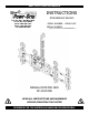
KEEP FOR FUTURE REFERENCE INSTRUCTIONS International Version P.O.
TABLE OF CONTENTS SPECIFICATIONS ............................................................................................................ 3 WARNINGS ..................................................................................................................... 4 OPERATING FEATURES ................................................................................................... 5 ASSEMBLY .............................................................................................................
MAINTENANCE ............................................................................................................. 23 INSPECTION SCHEDULE ............................................................................................................. 23 Every-Lift Inspection ..................................................................................................................................23 Frequent Inspection ...............................................................................
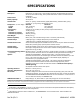
SPECIFICATIONS Model Number: MR1611LDC Description: Designed for use with a crane or other hoisting equipment, the MR1611LDC lifter employs vacuum to hold a load for lifting, and it provides manual 360° rotation movements for load manipulation.
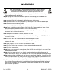
WARNINGS Powr-Grip is pleased to offer the most reliable vacuum lifters available. Despite the high degree of security provided by this product, certain precautions must be observed to protect the operator and others. Always wear personal protective equipment that is appropriate for the material being handled. Follow trade association guidelines. Always operate the lifter under conditions approved for its design (see INTENDED USE: OPERATING ENVIRONMENT).
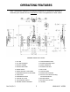
OPERATING FEATURES Note: Components featured in the following instructions for assembling, operating or maintaining the vacuum lifter are underlined on their first appearance in each section. Standard MR1611LDC shown.
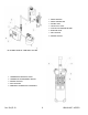
1 RADIO RECEIVER 2 RADIO TRANSMITTER 3 STROBE LIGHT 4 VACUUM LIFT LIGHT 5 LOW VACUUM WARNING BUZZER 6 ENABLE BUTTON 7 APPLY BUTTON 8 RELEASE BUTTON OPTIONAL REMOTE CONTROL SYSTEM 1 TRANSMISSION INDICATOR LIGHT 2 TRANSMITTER POWER/ENABLE SWITCH 3 RELEASE BUTTONS 4 APPLY BUTTONS 5 EMERGENCY TRANSMITTER DISCONNECT OPTIONAL RADIO TRANSMITTER Rev 30.
ASSEMBLY TO SET UP THE LIFTER 1) Open the shipping container and remove all materials for restraining or protecting the vacuum lifter. Save the container for use whenever the lifter is transported. 2) Suspend the lifter from a crane as follows: Select hoisting equipment (crane and hoist, when applicable) rated to carry the maximum load weight plus the lifter weight (see SPECIFICATIONS: Maximum Load Capacity and Lifter Weight).
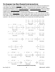
TO CHANGE THE PAD FRAME CONFIGURATION This lifter offers a variety of pad frame configurations to accommodate different load dimensions and weights (see illustrations on following page). Configurations are created by installing or removing the pad frame’s outer, removable sections and removable pad arms, and/or by rotating the pad frame’s rotating pad arms. Some configurations also require the lift bar extension to be installed (see To Install the Lift Bar Extension to follow).
To Install (and Remove) the Lift Bar Extension The lift bar extension must be used whenever the pad frame’s removable sections are attached. Otherwise, the extended pad frame would strike the lift bail during rotation. The lift bar extension can be removed whenever the removable sections are not attached to the pad frame. 1) Support the lifter so that hoisting equipment is not required to hold it upright.
To Install (and Remove) Removable Pad Arms 1) Insert the end of a removable pad arm in one socket on the pad frame, so that the holes align for the cotterless hitch pin. 2) Secure the removable pad arm in the pad frame by pushing a cotterless hitch pin through the holes until the retaining ball emerges on the far side of the pad frame socket. COTTERLESS HITCH PIN 1 PULL RING 2 RETAINING BALL 3) Remove the end of the quick connector from the spring clip on the pad arm.
INTENDED USE LOAD CHARACTERISTICS WARNING: This lifter is NOT intended for lifting hazardous materials, such as explosives or radioactive substances. The operator must verify that the lifter is intended to handle each load, in accordance with the following requirements: • The load must not exceed the maximum allowable weight specified under Load Capacity (see SPECIFICATIONS). • The load must be a single piece of nonporous or semiporous material with a flat and relatively smooth contact surface.
OPERATING ENVIRONMENT The operator must determine whether the lifter is intended to be used in each work environment, in accordance with the following restrictions: WARNING: Never use lifter in dangerous environments. • This lifter is not intended for use in any environment that is inherently dangerous to the operator or likely to compromise the lifter's ability to function. Environments containing explosives, caustic chemicals and other dangerous substances must be avoided when using the lifter.
OPERATION BEFORE USING THE LIFTER The operator must determine whether the lifter is capable of performing each intended task, in accordance with the SPECIFICATIONS and INTENDED USE sections of this INSTRUCTIONS manual. In addition, all of the following preparations must be completed prior to lifting any load. Taking Safety Precautions The operator must be trained in all relevant industry and regulatory standards for the operation of the vacuum lifter in its geographical location (eg, ASME B30.
In order to be considered clearly audible, the alarm volume must exceed ambient noise by at least 15 dBA at the operator position.4 Since the Maximum Alarm Volume is 103 dBA, ambient noise must not exceed 88 dBA under any circumstances. Furthermore, if ambient noise measures 88 dBA, the alarm volume must be set to maximum and the operator must remain within 2 ft [60 cm] of the warning buzzer, in order for it to be effective.
TO APPLY THE PADS TO A LOAD Powering up the Lifter Place the lifter's power switch in the ON ( ) position.6 The blue power light remains illuminated while the lifter is powered up. Keep the power switch in the ON position while lifting a load. Any power interruption during a lift could result in the release of a load and possible injury to the operator or others (see TO LIFT AND MOVE THE LOAD: In Case of Power Failure to follow). WARNING: Never turn power off while lifting.
Sealing the Pads against the Load The apply/release switch is located on the movable control pendant. The movable control pendant allows the vacuum controls to be moved away from the lifter, so that the operator can control airflow at a distance equal to the length of the pendant cord. WARNING: Do not disconnect control pendant during lifter operation. The movable control pendant is not intended to be disconnected during lifter operation.
Reading the Vacuum Gauge The vacuum gauge indicates the current vacuum level in the lifter’s vacuum system. The green range indicates vacuum levels sufficient for lifting the maximum load weight, whereas the red range indicates vacuum levels that are not sufficient for lifting the maximum load weight. The gauge needle should show a sudden surge in vacuum as the vacuum pads seal against the load.
TO LIFT AND MOVE THE LOAD WARNING: Never attempt to lift load when lifter is in horizontal orientation. Load Capacity and the Lift Light A lifter’s Load Capacity is rated at a vacuum level of 16" Hg [-54 kPa] (see SPECIFICATIONS). After the lifter has attained this level, the vacuum pumps turn off automatically, to conserve battery energy. At the same time, the green vacuum lift light turns on, to indicate that the lifter is ready to lift the maximum load weight.
Monitoring the Low Vacuum Warning Buzzer (if applicable) If the lifter is equipped with a low vacuum warning buzzer, an alarm sounds until the lifter attains sufficient vacuum to lift the maximum load weight (see SPECIFICATIONS: Load Capacity). After the lifter has attained this vacuum level, the alarm stops sounding, to indicate that the lifter is ready to lift the load. WARNING: Never attempt to lift load while alarm is sounding.
TO ROTATE THE LOAD EDGEWISE WARNING: Make sure load is positioned correctly on lifter (see TO APPLY); unbalanced loads may rotate unexpectedly when latch is disengaged. Remember that the load is longer in its diagonal dimensions than in its side dimensions. Make sure there is sufficient clearance for the load to rotate without contacting the operator or any nearby objects. Keep the load under control at all times, using hand cups or other appropriate means.
TO RELEASE THE PADS FROM THE LOAD WARNING: Load must be fully supported before releasing vacuum pads. Make sure the load is at rest and fully supported. Then turn the apply/release switch on the movable control pendant to the “RELEASE” position (counter-clockwise) to force air into the vacuum pads, quickly breaking the vacuum seal. Continue to hold the apply/release switch in this position until the pads disengage completely from the load.
AFTER USING THE LIFTER Leave the apply/release switch in the neutral position and place the power switch in the OFF position ( ). The blue indicator light shuts off when the operator powers down the lifter. If the lifter is equipped with a Remote Control System, also turn off the radio transmitter. CAUTION: Do not set the lifter against any surfaces which could soil or damage the vacuum pads.
MAINTENANCE WARNING: Always make sure battery is disconnected before servicing lifter. Note: One or more wiring diagrams are provided in the final section of this INSTRUCTIONS manual for reference when servicing the lifter or trouble-shooting a deficiency. INSPECTION SCHEDULE Perform inspections routinely, according to the following frequency schedule: Every-Lift Inspection • Examine the vacuum pads and load surface for contamination or debris (see VACUUM PAD MAINTENANCE to follow).
CAUTION: Be sure to use appropriate cleaning methods for each type of electrical component, as specified by codes and standards. Improper cleaning can damage components. • Keep a written record of all Periodic Inspections. If any deficiency is detected during the inspection, correct it before using the lifter. If necessary, return the lifter to Wood’s Powr-Grip or an authorized dealer for repair (see LIMITED WARRANTY).
vacuum switch, consult the VACUUM SWITCH ADJUSTMENT discussion for inspection, testing and adjustment procedures. MAINTENANCE SCHEDULE Unless specified elsewhere in this INSTRUCTIONS manual, the lifter does not require maintenance on a routine basis. Instead, maintenance must be performed whenever a deficiency is indicated by routine inspections or tests. Any maintenance warranted must be performed before resuming normal operation of the lifter.
BATTERY RECHARGE CAUTION: Charge battery only while lifter’s power switch is in the OFF ( ) position. Operating the lifter when the battery charger is connected to an AC power source could result in permanent damage to the charger. Only use a battery charger supplied by or approved by Wood's Powr-Grip; other chargers may reduce battery life. Charge the battery as soon as possible after any extended use of the lifter, or whenever the battery gauge indicates diminished energy (see BATTERY TEST preceding).
VACUUM PAD MAINTENANCE Friction Coefficient The friction coefficient represents the lifter's ability to resist load slippage when the load is oriented in any position except horizontal. If the contact surfaces of either the load or the vacuum pads are not clean, dry and in good condition, slippage is more likely to occur. The Load Capacity of most Powr-Grip lifters is based on a friction coefficient of 1 (only Flat Lifters are exempt from this requirement).
WARNING: Never use unauthorized rubber cleaners or conditioners to clean vacuum pad. To prevent liquid from contaminating the vacuum system during cleaning, cover the suction hole in the recess for the filter screen or make sure the pad faces downward. Use a clean sponge or lint-free cloth to apply an authorized cleanser and wipe the pad face clean. A toothbrush (or similar brush with bristles that do not harm rubber) may be used to remove contaminates clinging to sealing edges.
REMOTE CONTROL SYSTEM TEST If the lifter is equipped with a Remote Control System, perform this test in the environment where the lifter is normally employed. Use the radio transmitter to activate each of the remote functions.20 Vary the location and distance of the transmitter in relation to the lifter, to ensure that transmissions are effective in a variety of circumstances. This may require assistance from someone near the lifter, to verify that functions are being performed as intended.
AIR FILTER MAINTENANCE (for 4.4 oz [130 ml] bowl size filters) Filter Function and Conditions Requiring Service An air filter prevents solid particles and liquid from contaminating components in the vacuum system. CAUTION: Examine air filter regularly and empty when necessary. Liquid must not contact any portion of the filter element; remove trapped liquid regularly. Replace the element if it has an overall dirty appearance, or if there is a noticeable increase in the time required to attain full vacuum.
VACUUM PUMP MAINTENANCE ― THOMAS 2907CDC22/12 WARNING: Before proceeding with any maintenance, disconnect power source. If the vacuum pump takes too long to attain full vacuum, it may require maintenance (see OPERATING FEATURES for location of pump). Replace the diaphragms, valve flappers or head gaskets as necessary to obtain acceptable pump performance (see REPLACEMENT PARTS LIST). Perform the following procedures on both heads of the pump.
VACUUM PUMP MAINTENANCE − DYNAFLO DV1032102 WARNING: Before proceeding with any maintenance, disconnect power source. If the vacuum pump takes too long to attain full vacuum, it may require maintenance. Replace the diaphragm, gasket/flap valves or (when preferable) the entire head assembly22 (see REPLACEMENT PARTS LIST), as necessary to obtain acceptable pump performance. CAUTION: Do not over-tighten the head screws, because this may damage the threads in the pump body.
VACUUM SWITCH ADJUSTMENT Vacuum Switch Function23 A vacuum switch controls the vacuum pump and the vacuum lift light (see OPERATING FEATURES for location of vacuum switch). When the power switch located on the lifter is in the ON position ( ), activating the apply function engages the vacuum pump, which evacuates the vacuum pads.
maintain a higher vacuum level.25 Otherwise, the lifter would not maintain sufficient vacuum to lift the maximum load weight. Adjustment Procedure WARNING: Load capacity decreases whenever vacuum switch is adjusted to maintain lower vacuum level. 1) Using a 1/4" open-end wrench (as provided), turn the adjustment screw about 1/6th turn at a time (approximately one flat of the screw head).
REPLACEMENT PARTS LIST Stock No.
LIMITED WARRANTY Powr-Grip products are carefully constructed, thoroughly inspected at various stages of production, and individually tested. They are warranted to be free from defects in workmanship and materials for a period of one year from the date of purchase. If a problem develops during the warranty period, follow the instructions hereafter to obtain warranty service. If inspection shows that the problem is due to defective workmanship or materials, Powr-Grip will repair the product without charge.
Rev 30.
Rev 30.
Rev 30.
Rev 30.