KEEP FOR FUTURE REFERENCE INSTRUCTIONS International Version P.O.
SPECIFICATIONS Description: Model Number: Pad Spread:1 Maximum: Minimum: Lifter Weight: Load Capacity: Per-Pad: Maximum: Designed for use with a crane or other hoisting equipment, the FLEX-HV11AIR lifters employ vacuum to hold a load for lifting in the flat orientation.
WARNINGS Powr-Grip is pleased to offer the most reliable vacuum lifters available. Despite the high degree of security provided by this product, certain precautions must be observed to protect the operator and others. Always wear personal protective equipment that is appropriate for the material being handled. Follow trade association guidelines. Always operate the lifter under conditions approved for its design (see INTENDED USE: OPERATING ENVIRONMENT).
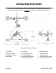
OPERATING FEATURES Note: Components featured in the following instructions for assembling, operating or maintaining the vacuum lifter are underlined on their first appearance in each section. Standard FLEX2HV11AIR shown. 1 LIFT SPOOL 5 VACUUM PAD 9 PRESSURE GAUGE 2 CONTROL HANDLE 6 VACUUM RESERVE TANK 10 AIR SUPPLY VALVE 3 MOVABLE PAD MOUNT 7 AIR FILTER (LARGE) 11 VACUUM GAUGE 4 PAD FRAME 8 AIR PRESSURE REGULATOR 12 VACUUM CONTROL VALVE and AIR FILTER (SMALL) Rev 8.
ASSEMBLY 1) Open the shipping container and remove all materials for restraining or protecting the vacuum lifter. Save the container for use whenever the lifter is transported. 2) Suspend the lifter from a crane as follows: Select hoisting equipment (crane and hoist, when applicable) rated to carry the maximum load weight plus the lifter weight (see SPECIFICATIONS: Maximum Load Capacity and Lifter Weight).
INTENDED USE LOAD CHARACTERISTICS WARNING: This lifter is NOT intended for lifting hazardous materials, such as explosives or radioactive substances. The operator must verify that the lifter is intended to handle each load, in accordance with the following requirements: • The load must not exceed the maximum allowable weight specified under Load Capacity (see SPECIFICATIONS). • The load must be a single piece of nonporous or semiporous material with a flat and relatively smooth contact surface.
OPERATING ENVIRONMENT The operator must determine whether the lifter is intended to be used in each work environment, in accordance with the following restrictions: WARNING: Never use lifter in dangerous environments. • This lifter is not intended for use in any environment that is inherently dangerous to the operator or likely to compromise the lifter's ability to function. Environments containing explosives, caustic chemicals and other dangerous substances must be avoided when using the lifter.
OPERATION BEFORE USING THE LIFTER The operator must determine whether the lifter is capable of performing each intended task, in accordance with the SPECIFICATIONS and INTENDED USE sections of this INSTRUCTIONS manual. In addition, all of the following preparations must be completed prior to lifting any load. Taking Safety Precautions The operator must be trained in all relevant industry and regulatory standards for the operation of the vacuum lifter in its geographical location (eg, ASME B30.
TO CHANGE PAD POSITIONS The lifter can accommodate various load dimensions, depending on the position of the movable pad mounts on the pad frame. Move the pad mounts inward or outward on the pad frame as needed to provide adequate support across the load surface. The pad mounts must be arranged symmetrically, to keep the lifter balanced. WARNING: Make sure vacuum hoses are coiled or routed so they do not become entangled, kinked or punctured.
Positioning the Lifter on the Load Make certain that the contact surfaces of the load and all vacuum pads are free of any contaminates that could harm the pads or prevent them from sealing against the load (see MAINTENANCE: VACUUM PAD MAINTENANCE).5 WARNING: To avoid accidental load release, always center lifter’s pad frame on load.
Vacuum Level on Optimal Surfaces When the lifter is attached to clean, smooth, nonporous load surfaces, it should be able to maintain a vacuum level in the green range on the vacuum gauge, except when used at high elevations (see SPECIFICATIONS: Operating Elevation). If not, perform the VACUUM TEST (see MAINTENANCE) to determine whether there is a deficiency in the vacuum generating system.
Monitoring the Vacuum Gauge The vacuum gauge must remain completely visible to the operator, so that it can be monitored throughout the entire lift. WARNING: Vacuum gauge must be visible to operator throughout entire lift. The lifter’s vacuum pump runs continuously to maintain sufficient vacuum for lifting the maximum load weight. If the vacuum system experiences leakage while the lifter is attached to the load, the vacuum gauge signals the reduction in vacuum to the operator.
TO RELEASE THE PADS FROM THE LOAD WARNING: Load must be fully supported before releasing vacuum pads. When the load is at rest and fully supported, move the lever on the vacuum control valve to the "RELEASE" position: Pull upward on the lever's knob, move the lever all the way back (towards operator) and then release it. This forces air into the vacuum pads, quickly breaking the vacuum seal. After the pads have disengaged completely from the load, move the lifter away.
MAINTENANCE WARNING: Always make sure power source is disconnected before servicing lifter. INSPECTION SCHEDULE Perform inspections routinely, according to the following frequency schedule: Every-Lift Inspection • Examine the vacuum pads and load surface for contamination or debris (see VACUUM PAD MAINTENANCE to follow). • Examine the vacuum pads, controls and indicators for visual damage (see VACUUM PAD MAINTENANCE to follow).
If any deficiency is detected during the inspection, correct it before using the lifter. If necessary, return the lifter to Wood’s Powr-Grip or an authorized dealer for repair (see LIMITED WARRANTY). Infrequent Use If a lifter is used less than 1 day in a 2-week period, perform the Periodic Inspection each time before using the lifter. TESTING SCHEDULE Perform these tests when placing the lifter in service initially and each time following a repair or modification.
MAINTENANCE SCHEDULE Unless specified elsewhere in this INSTRUCTIONS manual, the lifter does not require maintenance on a routine basis. Instead, maintenance must be performed whenever a deficiency is indicated by routine inspections or tests. Any maintenance warranted must be performed before resuming normal operation of the lifter.
for cleaning. Do not use unauthorized rubber cleaners or conditioners, such as those intended for cleaning tires or vinyl surfaces, because those products can leave a hazardous film on vacuum pads which significantly reduces their lifting capacity (see Friction Coefficient preceding). The use of any unauthorized cleaning agent is prohibited because it could damage the pad and/or create a hazard to the operator or others. WARNING: Never use solvents, gasoline or other harsh chemicals to clean vacuum pad.
AIR FILTER MAINTENANCE (for 4.4 oz [130 ml] bowl size filters) Filter Function and Conditions Requiring Service An air filter prevents solid particles and liquid from contaminating components in the vacuum system. CAUTION: Examine air filter regularly and empty when necessary. Liquid must not contact any portion of the filter element; remove trapped liquid regularly. Replace the element if it has an overall dirty appearance, or if there is a noticeable increase in the time required to attain full vacuum.
AIR FILTER MAINTENANCE (for 1 oz [30 ml] bowl size filters) Filter Function and Conditions Requiring Service An air filter prevents solid particles and liquid from contaminating components in the vacuum system. CAUTION: Examine air filter regularly and empty when necessary. Liquid must not contact any portion of the filter element; remove trapped liquid regularly. Replace the element if it has an overall dirty appearance, or if there is a noticeable increase in the time required to attain full vacuum.
REPLACEMENT PARTS LIST Stock No. Description Qty. 66161 Vacuum Pump - Venturi-Type - 4-SCFM [113 liters/minute] 1 65443 Vacuum Hose - 3/8" [9.5 mm] ID (approx. 60" [153 cm] in length) 1 65430 Vacuum Hose - 7/32" [5.6 mm] ID * 65288 Air Supply Valve 1 65277 Vacuum Control Valve with Handle 1 65212 Check Valve - 1/4 NPT 1 65014 Pad Spring - Wave Type * 59028 Movable Pad Mount - 2-1/2" [63.5 mm] Tubing Size * 53130 Pad Fitting - Tee - 5/32" [4.
LIMITED WARRANTY Powr-Grip products are carefully constructed, thoroughly inspected at various stages of production, and individually tested. They are warranted to be free from defects in workmanship and materials for a period of one year from the date of purchase. If a problem develops during the warranty period, follow the instructions hereafter to obtain warranty service. If inspection shows that the problem is due to defective workmanship or materials, Powr-Grip will repair the product without charge.