
User guide

Rev 9.0/9-13 10 FLEX-HV11AC: #35032
TO CHANGE PAD POSITIONS
The lifter can accommodate various load dimensions, depending on the position of the movable
pad mounts on the pad frame. Move the pad mounts inward or outward on the pad frame as
needed to provide adequate support across the load surface. The pad mounts must be arranged
symmetrically, to keep the lifter balanced.
WARNING: Make sure vacuum hoses are coiled or routed so they do not become
entangled, kinked or punctured.
To position a pad mount, remove the cotterless hitch pin from the pad frame. While making sure
the vacuum hose does not get pinched, move the pad mount to the desired position and align
the holes for the pin. Push the pin through the holes until the retaining ball emerges on the far
side of the mount. On the opposite end of the pad frame, position the corresponding pad mount
at an equal distance from the center of the lifter. Before applying the vacuum pads to a load,
make sure that all vacuum hoses are routed correctly and will not interfere with lifter operation.
TO APPLY THE PADS TO A LOAD
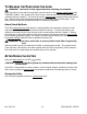
Powering up the Lifter
Make sure the lever on the vacuum control valve is in the center position (see TO RELEASE THE
PADS FROM THE LOAD: About Stand-By Mode to follow). Place the power switch in the ON ( )
position, to engage the vacuum pump.
6
The lifter is designed for the vacuum pump to run
continuously.
WARNING: Never turn power off while operating lifter; keep pump running
throughout lift.
The power switch must remain in the ON position while operating the lifter. Placing the power
switch in the OFF ( ) position during lifter operation could result in the release of the load and
possible injury to the operator (see TO LIFT AND MOVE THE LOAD: In Case of Power Failure to
follow).
6
After the power switch is placed in the ON position, the vacuum lift light may subsequently turn on, because the lifter is
operating in stand-by mode at this stage. However, this does
not
indicate that the lifter is ready to lift a load.