KEEP FOR FUTURE REFERENCE INSTRUCTIONS International Version P.O.
TABLE OF CONTENTS SPECIFICATIONS ............................................................................................................ 3 WARNINGS ..................................................................................................................... 4 OPERATING FEATURES ................................................................................................... 5 ASSEMBLY .............................................................................................................
MAINTENANCE ............................................................................................................. 15 INSPECTION SCHEDULE ............................................................................................................. 15 Every-Lift Inspection ..................................................................................................................................15 Frequent Inspection ...............................................................................
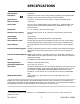
SPECIFICATIONS Model Number: FL1HV11DC Description: Designed for use with a crane or other hoisting equipment, the FL1HV11DC lifter employs vacuum to hold a load for lifting in the flat orientation. Power Source: 12 volts DC, 10 amps (with Thomas pump) or 3 amps (with Dynaflo pump) Battery Capacity: 7 amp-hours Vacuum Pad: One 10" [25 cm] nominal diameter, lipped (Model HV11), standard rubber, with #60 filter screen; Optional closed-cell foam ring for applications on rough or textured surfaces.
WARNINGS Powr-Grip is pleased to offer the most reliable vacuum lifters available. Despite the high degree of security provided by this product, certain precautions must be observed to protect the operator and others. Always wear personal protective equipment that is appropriate for the material being handled. Follow trade association guidelines. Always operate the lifter under conditions approved for its design (see INTENDED USE: OPERATING ENVIRONMENT).
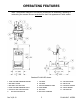
OPERATING FEATURES Note: Components featured in the following instructions for assembling, operating or maintaining the vacuum lifter are underlined on their first appearance in each section. Standard FL1HV11DC shown. 1 2 3 4 5 6 LOW VACUUM WARNING BUZZER BATTERY GAUGE BATTERY TEST BUTTON LOW VACUUM WARNING LIGHT Enclosure with VACUUM PUMP and VACUUM SWITCH Rev 3.
ASSEMBLY 1) Open the shipping container and remove all materials for restraining or protecting the vacuum lifter. Save the container for use whenever the lifter is transported. 2) Suspend the lifter from a crane as follows: Select hoisting equipment (crane and hoist, when applicable) rated to carry the maximum load weight plus the lifter weight (see SPECIFICATIONS: Maximum Load Capacity and Lifter Weight).
INTENDED USE LOAD CHARACTERISTICS WARNING: This lifter is NOT intended for lifting hazardous materials, such as explosives or radioactive substances. The operator must verify that the lifter is intended to handle each load, in accordance with the following requirements: • The load must not exceed the maximum allowable weight specified under Load Capacity (see SPECIFICATIONS). • The load must be a single piece of nonporous or semiporous material with a flat and relatively smooth contact surface.
OPERATING ENVIRONMENT The operator must determine whether the lifter is intended to be used in each work environment, in accordance with the following restrictions: WARNING: Never use lifter in dangerous environments. • This lifter is not intended for use in any environment that is inherently dangerous to the operator or likely to compromise the lifter's ability to function. Environments containing explosives, caustic chemicals and other dangerous substances must be avoided when using the lifter.
OPERATION BEFORE USING THE LIFTER The operator must determine whether the lifter is capable of performing each intended task, in accordance with the SPECIFICATIONS and INTENDED USE sections of this INSTRUCTIONS manual. In addition, all of the following preparations must be completed prior to lifting any load. Taking Safety Precautions The operator must be trained in all relevant industry and regulatory standards for the operation of the vacuum lifter in its geographical location (eg, ASME B30.
CAUTION: Examine each air filter regularly, and empty when necessary. The lifter is equipped with one or more air filters to help protect the vacuum system from contaminants. In order for a filter to function, the operator must empty the filter bowl before enough liquid accumulates to contact any portion of the filter element (see MAINTENANCE: AIR FILTER MAINTENANCE).
Reading the Vacuum Gauge The vacuum gauge indicates the current vacuum level in the lifter’s vacuum system. The green range indicates vacuum levels sufficient for lifting the maximum load weight, whereas the red range indicates vacuum levels that are not sufficient for lifting the maximum load weight. The gauge needle should show a sudden surge in vacuum as the vacuum pad seals against the load.
TO LIFT AND MOVE THE LOAD Load Capacity and the Warning Light The lifter's Load Capacity is rated at a vacuum level of 16" Hg [-54 kPa] (see SPECIFICATIONS). After the lifter has attained this level, the vacuum pump turns off automatically, to conserve battery energy. At the same time, the low vacuum warning light turns off, to indicate that the lifter is ready to lift the maximum load weight. WARNING: Never attempt to lift load while red warning light is illuminated.
Monitoring the Low Vacuum Warning Buzzer Using the low vacuum warning buzzer requires minimal interaction from the operator. The warning buzzer sounds an alarm until the lifter attains sufficient vacuum to lift the maximum load weight (see SPECIFICATIONS: Load Capacity). After the lifter has attained this vacuum level, the alarm stops sounding, to indicate that the lifter is ready to lift the load. WARNING: Never attempt to lift load while alarm is sounding.
TO RELEASE THE PAD FROM THE LOAD WARNING: Load must be fully supported before releasing vacuum pad. When the load is at rest and fully supported, pinch the valve release lever against the valve handle, to unlatch the handle. Then push the valve handle inward to the “RELEASE” position (power off), as shown. Do not attempt to move the lifter until the vacuum pad disengages completely from the load. TO RELEASE AFTER USING THE LIFTER Leave the valve handle in the “RELEASE” position (power off).
MAINTENANCE WARNING: Always make sure battery is disconnected before servicing lifter. INSPECTION SCHEDULE Perform inspections routinely, according to the following frequency schedule: Every-Lift Inspection • Examine the vacuum pads and load surface for contamination or debris (see VACUUM PAD MAINTENANCE to follow). • Examine the vacuum pads, controls and indicators for visual damage (see VACUUM PAD MAINTENANCE to follow). • Test the battery for adequate charge (see BATTERY TEST to follow).
If any deficiency is detected during the inspection, correct it before using the lifter. If necessary, return the lifter to Powr-Grip or an authorized dealer for repair (see LIMITED WARRANTY). Infrequent Use If a lifter is used less than 1 day in a 2-week period, perform the Periodic Inspection each time before using the lifter. TESTING SCHEDULE Perform these tests when placing the lifter in service initially and each time following a repair or modification.
MAINTENANCE SCHEDULE Unless specified elsewhere in this INSTRUCTIONS manual, the lifter does not require maintenance on a routine basis. Instead, maintenance must be performed whenever a deficiency is indicated by routine inspections or tests. Any maintenance warranted must be performed before resuming normal operation of the lifter. BATTERY TEST The lifter is equipped with a battery gauge to help the operator evaluate whether the battery has adequate energy for lifting.
Identify the input voltage marked on the battery charger, and plug it in to an appropriate power source.11 The power source must be equipped with a ground fault circuit interrupter, in order to reduce the risk of electrical shocks. WARNING: Power source must be equipped with ground fault circuit interrupter. Usually a battery takes no more than 16 hours to charge completely, after which the charger shuts off automatically.
• Filter screen missing from pad face: This screen helps prevent debris from plugging the vacuum hose and the air filter. Replace any missing screen immediately (see REPLACEMENT PARTS LIST). • Nicks, cuts or abrasions in sealing edges: Pad damage can reduce the lifting capacity of the lifter. Replace any damaged pad immediately (see REPLACEMENT PARTS LIST). WARNING: Replace vacuum pad if sealing edge has any nicks, cuts or abrasions. • Wear, stiffness or glaze: See Friction Coefficient preceding.
VACUUM TEST Test the vacuum system for leakage routinely, as directed in the preceding INSPECTION and TESTING SCHEDULES. 1) Clean the face of each vacuum pad as previously directed (see VACUUM PAD MAINTENANCE: Cleaning). 2) Apply the lifter to a clean, smooth, nonporous surface. The surface should be flat or possess no more curvature than the lifter is designed for (if any).
AIR FILTER MAINTENANCE − SMALL (for 1 oz [30 ml] bowl size filters) Filter Function and Conditions Requiring Service An air filter prevents solid particles and liquid from contaminating components in the vacuum system. CAUTION: Examine air filter regularly and empty when necessary. Liquid must not contact any portion of the filter element; remove trapped liquid regularly.
VACUUM PUMP MAINTENANCE − DYNAFLO DV1032102 WARNING: Before proceeding with any maintenance, disconnect power source. If the vacuum pump takes too long to attain full vacuum, it may require maintenance. Replace the diaphragm, gasket/flap valves or (when preferable) the entire head assembly15 (see REPLACEMENT PARTS LIST), as necessary to obtain acceptable pump performance. CAUTION: Do not over-tighten the head screws, because this may damage the threads in the pump body.
VACUUM PUMP MAINTENANCE − THOMAS 107CDC20 WARNING: Before proceeding with any maintenance, disconnect power source. If the vacuum pump (14) takes too long to attain full vacuum, it may require maintenance. Replace the diaphragm, valve flappers or head gasket as necessary to obtain acceptable pump performance (see REPLACEMENT PARTS LIST). Replacing the Diaphragm 1) Remove the four head screws (1) and remove the head (2).
VACUUM SWITCH ADJUSTMENT Vacuum Switch Function17 A vacuum switch controls the low vacuum warning light and the vacuum pump (see OPERATING FEATURES for location of vacuum switch): The valve handle activates the warning light and the pump, which evacuates the vacuum pads.18 After the lifter attains a vacuum level sufficient for lifting the maximum load weight (hereafter, “minimum lifting level”), the vacuum switch automatically turns off the pump and the warning light.
Adjustment Procedure WARNING: Lifting capacity decreases whenever vacuum switch is adjusted to maintain lower vacuum level. 1) Using a 1/4" open-end wrench (as provided), turn the adjustment screw about 1/6th turn at a time (approximately one flat of the screw head). To maintain a lower vacuum level, turn the screw clockwise (when viewing vacuum switch from end with electrical connectors).
REPLACEMENT PARTS LIST Stock No. Description Qty.
LIMITED WARRANTY Powr-Grip products are carefully constructed, thoroughly inspected at various stages of production, and individually tested. They are warranted to be free from defects in workmanship and materials for a period of one year from the date of purchase. If a problem develops during the warranty period, follow the instructions hereafter to obtain warranty service. If inspection shows that the problem is due to defective workmanship or materials, Powr-Grip will repair the product without charge.
Rev 3.