KEEP FOR FUTURE REFERENCE INSTRUCTIONS P.O.
TABLE OF CONTENTS SPECIFICATIONS ............................................................................................................ 2 WARNINGS ..................................................................................................................... 2 OPERATING FEATURES ................................................................................................... 3 ASSEMBLY .............................................................................................................
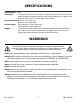
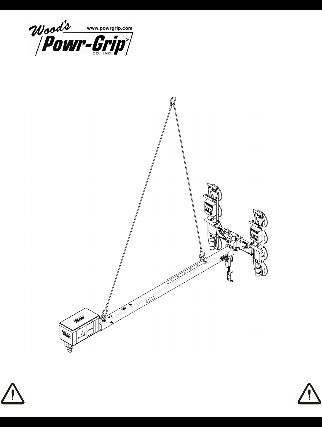
SPECIFICATIONS Model Number: CB1 Description: In combination with a P2 vacuum lifter, this equipment allows loads to be positioned under overhangs by extending the lifter away from the lifting slings or rigging, and it allows the lifter to tilt in a "reverse angle", when needed.
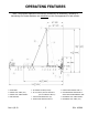
OPERATING FEATURES Note: Components featured in the following instructions for assembling, operating or maintaining the Counter-Balancer are underlined on their first appearance in each section. 1 HOOK POINT 5 P2 CHANNEL LIFTER (inverted) 2 PRIMARY LIFT SLING (12 ft) 6 P2 LIFT SPOOL (alternate attachment 3 PRIMARY LIFT SLING SHACKLE 4 MAIN SECTION Rev 1.
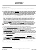
ASSEMBLY Set-Up Procedure 1) Remove the top of the shipping crate and all devices for restraining the Counter-Balancer during shipping.
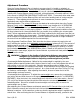
Adjustment Procedure Since the Counter-Balancer/Lifter unit tends to see-saw when it is loaded or unloaded, an adjustable counterweight arm, control lines and ballast placed in a counterweight enclosure are used to keep it level. In order to make the unit hang at a desirable angle for the application (usually with Counter-Balancer nearly horizontal), some adjustment is normally required. Refer to the charts in SUGGESTED CONDITIONS TO KEEP UNIT LEVEL.
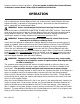
OPERATION section of these instructions. If you are unable to adjust the Counter-Balancer as directed, contact Wood's Powr-Grip for additional information. OPERATION Prior to operating the Counter-Balancer/Lifter unit, make sure the Counter-Balancer has been adjusted correctly, as directed in the preceding section. Also make sure that all hardware is secure, along with the counterweight ballast. WARNING: Secure counterweight ballast before moving Counter-Balancer.
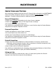
MAINTENANCE INSPECTIONS AND TESTING When performing inspections and tests of the P2 Channel Lifter as directed in the MAINTENANCE section of the lifter's instruction manual, be sure to include the Counter-Balancer whenever applicable. Consult the following topics for additional directions. Every-Lift Inspection: • Examine the lift shackles and shackle pins for signs of wear or damage. • Examine the lift slings for fraying or other signs of wear or damage. • Be sure all fasteners are secure before use.
REPLACEMENT PARTS LIST Stock No. Description Qty. 65330 ¾" Stock Diameter Anchor Shackle with Safety Pin 3 65324AM Wire Rope Sling - ½" Dia. x 12' Length - 2.5 Ton Capacity 1 65324 Wire Rope Sling - ½" Dia. x 13' Length - 2.
SUGGESTED CONDITIONS TO KEEP UNIT LEVEL CHART 1 A LOAD (lbs) 0 100 200 300 400 500 600 700 800 900 1000 1100 1200 1300 1400 CHART 2 A LOAD (lbs) SHORTEST REACH, LIFT POSITION #6 B C D OVERALL COUNTERWEIGHT LENGTH ARM BALLAST (inches) POSITION ID. (lbs) 156 156 156 156 168 180 180 192 192 204 204 204 216 216 216 #A #A #A #A #B #C #C #D #D #E #E #E #F #F #F 0 0 11 37 19 3 21 4 18 1 14 27 8 19 30 LONGEST REACH, LIFT POSITION #1 B C D OVERALL COUNTERWEIGHT LENGTH ARM BALLAST (inches) POSITION ID.
LIMITED WARRANTY Powr-Grip products are carefully constructed, thoroughly inspected at various stages of production, and individually tested. They are warranted to be free from defects in workmanship and materials for a period of one year from the date of purchase. If a problem develops during the warranty period, follow the instructions hereafter to obtain warranty service. If inspection shows that the problem is due to defective workmanship or materials, Powr-Grip will repair the product without charge.