
Product Manual

11. If the wire is going to be routed under the light,
use the foam gasket as a template, mark the hole
location and drill to size 5/16”. Deburr the drilled
hole and insert the provided rubber grommet into
the hole. The rubber grommet will ensure that there
are no sharp edges that could damage the wires or
cause a short circuit. IMPORTANT: If waterproofing
is required, use silicone sealant around wires and
rubber grommet.
12. Secure the base of the warning light to the vehicle
using only the hardware provided. To prevent
vibration and water leaks always use the rubber
gasket provided.
13. The power plug will not be used, cut the plug from
the cable, the plug can be discarded.
14. Carefully remove about 2” of the power cable’s
black vinyl outer cover. This will expose three (3)
wires; red, black and yellow. Inspect each wire to ensure that the insulation was not cut when removing the vinyl outer
cover.
15. RED WIRE: Is connected to (+)12 volts. Connect the red wire to the vehicles fuse block or the (+) positive battery
post. IMPORTANT: Always protect the vehicle’s electrical circuit with a five (5)-amp fuse (not included). Remove fuse
from the inline fuse holder until all wiring is completed. NOTE: This switch will control the light’s power on/off.
16. BLACK WIRE: Is connected to an on/off switch (not provided).
17. SWITCH’S OTHER TERMINAL: Is connected to ground, by placing the wire under the battery’s (-) negative post or
any metal body bolt that is clean of paint and rust.
18. YELLOW WIRE: Is connected to a normally open momentary on/off switch (not provided).
19. MOMENTARY SWITCH’S OTHER TERMINAL: Is connect to ground, by placing the wire under the battery’s (-)
negative post or any metal body bolt that is clean of paint and rust. NOTE: This switch will control the light’s flash pattern.
POWERING WARNING LIGHT WHEN HARD WIRED
20. Insert the fuse back into the fuse holder and position the switch to ON. The light will turn on and operate.
CHANGING LIGHT PATTERN: There are three (3) different light patterns to choose from.
21. HARD WIRED USING MOMENTARY SWITCH: Press and release the momentary switch and the light pattern will
change. Each time the pattern switch is pressed the light pattern will change.
CLEANING:
A scratched, dull or dirty lens can cause a reduction in brightness of warning light. Never use a caustic or petroleum base cleaner on
any surface of the warning light. For best cleaning results, always use household glass cleaner or mild soap with a soft lint free rag
.
ANY EXPRESSED WARRANTY NOT PROVIDED HEREIN IS EXCLUDED AND DISCLAIMED. THE IMPLIED WARRANTIES OF
MERCHANTABILITY AND OF FITNESS FOR A PARTICULAR PURPOSE ARE EXPRESSLY LIMITED TO A TERM OF THREE
(3) MONTHS. UNDER NO CIRCUMSTANCES SHALL WOLO BE LIABLE TO PURCHASER OR ANY OTHER PERSON FOR
ANY SPECIAL OR CONSEQUENTIAL DAMAGES, WHETHER ARISING OUT OF BREACH OF WARRANTY OR OTHERWISE.
To obtain warranty service, return the product prepaid, and include the original bill of sale showing the date of purchase.
Provide with the return a brief description of the problem with a daytime telephone number. Also, include with the return a
check or money order in the amount of $20.00 to cover return shipping.
Mail to:
Wolo Manufacturing Corp.
Attn: Warranty Service
One Saxwood Street, Deer Park, NY 11729
E-mail: tech@wolo-mfg.com
© 2018-2019 Wolo Mfg. Corp.
All Rights Reserved.
WARRANTY
Wolo Manufacturing Corporation (“Wolo”) warranties to the original purchaser, for three months from the date of purchase,
that this product is free from defects in workmanship and materials. If there is such a proven defect, Wolo, at its option, will
either repair or replace the item free of charge, if it is returned to Wolo within three months from the date of purchase together
with proof of purchase as described below. Wolo reserves the right to inspect any defect prior to settling any warranty claim by
repair or replacement. This warranty is limited as above provided and Wolo will not be responsible for fire or other casualty or
accident, due to neglect, abuse, abnormal use, modifications, faulty installation of this product, or natural causes.
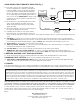
HARD WIRING FOR PERMANENT MOUNTING Fig. 3
Fig. 3
5 AMP FUSE
Not provided
12-VOLT DC
+ –
SWITCH
Not Provided
MOMENTARY
SWITCH
Not Provided
LIGHT
RED
BLACK
GROUND
GROUND
YELLOW