
User guide

8 21 068: M P E G-3 27 0 & 4290 Use r Guide
© 20 13 Wo h ler Tec hn ol ogi e s, In c . A l l r ig h ts re se rved.
11
C hap te r 1 Installation
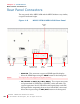
Re a r P ane l Co n ne cto rs
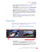
• RS-485 I/O (RJ-45): These two ports are used for UMD and
tally remote control.
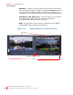
• Ethernet (RJ-45): This connector is used for network
communications and MPEG input to each of the two screens.
• Tally and GPI (RJ-45): This 8-pin connector controls the tally
lights on the front panel (2 pins) and allows remote control of the
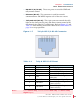
unit through the other five available pins. Refer to Figure 1–7 and
Table 1–1 when making connections. Refer to the GPI-In Menu on
page 39 to set up operation.
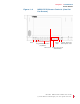
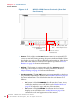
Figure 1–7 Tally & GPI-I/O RJ-45 Connector
Table 1–1 Tally & GPI RJ-45 Pinout
Pin Name Function
1 Tally Red Red Tally Signal
2 Tally Green Green Tally Signal
3 GPI-In 3 General Purpose Input 3
4 GPI-In 4 General Purpose Input 4
5 Gnd
Ground Return for signals on all
other pins
6 GPI-In 5 General Purpose Input 5
7 GPI-Out 7
General Purpose Output 7
(future release)
8 GPI-Out 8
General Purpose Output 8
(future release)
N ote:
For a Yellow Tally, activate both the Red Tally and Green Tally
Signal inputs.