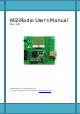
WIZ-iRadio User’s Manual (Ver. 1.0) ©2008 WIZnet Inc. All Rights Reserved. For more information, visit our website at www.wiznet.co.
WIZ-iRadio User’s Manual Document History Information Revision Date Description V1.0 May 1, 2008 Original Document 2 © Copyright 2008 WIZnet Inc.
WIZ-iRadio User’s Manual WIZnet’s Online Technical Support If you have something to ask about WIZnet Products, Write down your question on Q&A Board in WIZnet website (www.wiznet.co.kr). WIZnet Engineer will give an answer as soon as possible. 3 Technical Support: support@wiznet.co.kr Sales & Distribution: sales@wiznet.co.kr For more information, visit our website at http://www.wiznet.co.kr © Copyright 2008 WIZnet Inc.
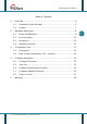
WIZ-iRadio User’s Manual Table of Contents 1. 2. 3. 4. 5. Overview ................................................................................ 6 1.1. Evaluation Board Package ................................................... 6 1.2. Feature ............................................................................ 7 Hardware description ................................................................ 8 2.1. Board Configuration ...........................................................
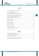
WIZ-iRadio User’s Manual Figures Figure 1. WIZ-iRadio Board Configuration .................................................................................................8 Figure 2. JTAG Interface ......................................................................................................................................9 Figure 3. Boot Mode Selection Jumper .......................................................................................................9 Figure 4.
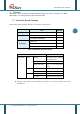
WIZ-iRadio User’s Manual 1. Overview WIZ-iRadio receives and plays the data through Internet protocols from a streaming server. With WIZ-i-Radio, you can play all Internet braodcast without PC. 1.1. Evaluation Board Package WIZ-iRadio Evaluation Board package is composed of below items. Item WIZ-iRadio -EVB Accessory Quantity WIZ-iRadio module 1 WIZ-iRadio Base Board 1 Power Adaptor (5V/500mA) 1 Software CD 1 UTP Cable 1 Remote Controller 1 Table 1.
WIZ-iRadio User’s Manual 1.2. Feature 1.2.1. Hardware Feauture WIZ - iRadio z MCU : ARM7TDMI 32-bit RISC CPU(STR710FZ2T6) z RAM : 2Mbytes external RAM z ROM : 256Kbytes Flash program memory(ARM7 Internal Flash) z LAN : WIZnet W5100 Hardwired TCP/IP Embedded Ethernet Controller z CODEC : VS1033C z Power Consumption : 175mA WIZ-iRadio Base Board z Power : DC 5V input z LCD : 128 x 64 graphic LCD with Blue Backlight z JTAG I/F : 2 x 10 male box header z SERIAL I/F : 1 x 4 male 2.
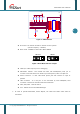
WIZ-iRadio User’s Manual 2. Hardware description 2.1. Board Configuration WIZ-iRadio-EVB is composed of a main module and a base board. The main module contains the MCU, RAM, Ethernet Controller, and CODEC that are responsible for the main functions of Internet Radio. In the base board, power for module operation and peripheral devices for input and output are located. 8 Figure 1. WIZ-iRadio Board Configuration z Power Jack : DC 5v INPUT(MIN 500mA), diameter(Φ4.2/Φ1.3) z RESET S/W : Reset Switch.
WIZ-iRadio User’s Manual 3.3V 3.3V R13 10K R10 10K R11 10K R12 10K J8 1 3 5 7 9 11 13 15 17 19 /JTRST JTDI JTMS JTCK JTDO /RESET DBGRQS R16 10K 2 4 6 8 10 12 14 16 18 20 R17 HEADER 10x2/SM 10K Figure 2. JTAG Interface z IR receiver : IR receiver module for remote control systems. (Carrier Frequency – 40.0kHz) z Boot mode : JUMPER to select MCU BOOT MODE. Figure 3. Boot Mode Selection Jumper z UART I/F : UART Output port for debugging.
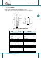
WIZ-iRadio User’s Manual 2.2. Pin Description The pin description of WIZ-iRadio module is detailed in Figure 4, below. As shown below, ‘J15’ is connected to ‘J5’ of base board, and ‘J14’ to ‘J6’ of base board. J15 3.3V 2 1 3.
WIZ-iRadio User’s Manual /CS_LCD O J15:15 Active low LCD chip select signal A0 O J15:16 Address 0 for LCD Control /WE0 O J15:17 Active low write enable output /RD O J15:18 D0 - D7 I/O /RESET TXOP Active low read signal for external memory J15:19 – J15:26 Data bus I J15:27 Active low reset signal O J14:1 The differential data is transmitted to the media on the TXOP/TXON signal TXON O J14:3 RXIP I J14:7 The differential data from the media is RXIN I J14:9 received on the R
WIZ-iRadio User’s Manual 2.3. Dimension 12 Figure 5. WIZ-iRadio Module Dimension (unit : mm) 2.4. Remote Controller Figure 6. WIZ-iRadio Remote Controller © Copyright 2008 WIZnet Inc.
WIZ-iRadio User’s Manual 3. Configuration Tool 3.1. Description In order to configure the WIZ-iRadio, the Configuration Tool program should be installed and used. Please download Install file from Software CD or WIZnet homepage (www.wiznet.co.kr) 13 . A B C D E F G H Figure 7. WIZ-iRadio Configuration Tool A. Module list : The Mac Address of all the modules on same subnet are displayed. B. F/W version : It shows the firmware version of WIZ-iRadio module. C.
WIZ-iRadio User’s Manual z Channel : It displays the list saved in the file “Server_list.txt”. “Server_list.txt” is created in the folder where Configuration Tool program is installed. E. Search : It searches for all modules installed on same subnet. F. Setting : It saves changed configurations. G. F/W upload : It is for upgrading the firmware. H. URLset : It saves changed channel information. 14 3.2. How to Use Configuration Tool - Examples A. Changing Network Information z z z B.
WIZ-iRadio User’s Manual 4. Firmware description 4.1. Firmware Structure The firmware of WIZ-iRadio is composed of Application and Boot. The role of Boot is for updating through the network. Therefore, JTAG ICE such as MultiICE is not required when developing. In the WIZ-iRadio, STR710FZ2 from STMicroelectronics is used. In the Flash of this MCU, Application and Boot firmware is written according to the memory map (below).
WIZ-iRadio User’s Manual There are RAM_MODE and FLASH. In the case of RAM_MODE, it is used for operating at the internal RAM after writing the F/W and downloading with JTAG device such as MultiICE. The FLASH is used for operating after writing in the flash memory of STR710FZ2. You can select one of them. For the not-used mode, mark it as commentary. The program starts from 0x400300000 of flash memory at the Boot. The scat file in the Boot folder is as below (please refer to Figure 9). 16 Figure 9.
WIZ-iRadio User’s Manual Execute RealView program and open the project file by selecting the menu “ProjectÎOpen project”. If you select “ProjectÎProject properties…”, “Project Properties” window is displayed. In this window, the modified part are shown in blue color. -. *PROJECT -- Source search 17 Figure 10. Compile - 1 -. *COMFILE=arm -- *Source You can add the source here. © Copyright 2008 WIZnet Inc.
WIZ-iRadio User’s Manual 18 Figure 11. Compile - 2 © Copyright 2008 WIZnet Inc.
WIZ-iRadio User’s Manual -. *COMFILE=arm -- *Preprocessor 19 Figure 12. Compile - 3 -. *ASSEMB:E=arm -- *Source © Copyright 2008 WIZnet Inc.
WIZ-iRadio User’s Manual 20 Figure 13. Compile - 4 -. *BUILD -- *Link Advanced Entry and Scatter files should be specified. © Copyright 2008 WIZnet Inc.
WIZ-iRadio User’s Manual 21 Figure 14. Compile - 5 The compile is processed after BuildÎCompile. © Copyright 2008 WIZnet Inc.
WIZ-iRadio User’s Manual 22 Figure 15. Compile - 6 After finishing compile, “network.axf” file is created in the folder of “REALVIEW\Debug”. In order to change this file to binary format, use ‘fromelf’. You can do it as below. It is created in the file “bin.bat” fromelf -bin -o network.bin network.axf After changing the file “network.axf” file to “network.bin”, if you execute “ROM_Tool.exe” program and input this file, “rom.bin” file is created in the folder of “romfile”. The role of “ROM_Tool.
WIZ-iRadio User’s Manual This “rom.bin” file can be updated through network by using Configuration Tool. 4.4. Firmware Operation Process 1) Initialize device a. GPIO b. Clock c. Setting EMI(External Memory Interface) CS1 for W5100, CS2 for external SRAM and CS3 for LCD d. Timer e. DMA request of VS1033 f. SPI interface for VS1033 g. I2C for EEPROM h.
WIZ-iRadio User’s Manual 1) Initialize device When power is supplied, all devices are initialized. GPIO is configured and clock is set. In regard to external memory interface, CS1 is connected to W5100, CS2 is to SRAM and CS3 is to LCD. According to this interface, set the ‘wait’ and ‘bus’ size. Timer 0 is used for DHCP request during lease time, and Timer 1 is for operation of IR Remote Controller. VS1033 chip used for decoding of MP3 and WMA is connected to MCU by SPI. The interrupt should be set.
WIZ-iRadio User’s Manual #define EEP_CONF 0x00 #define EEP_TEST (EEP_CONF) #define EEP_MAC (EEP_TEST+1) #define EEP_LIP (EEP_MAC + 6) #define EEP_SN (EEP_LIP + 4) #define EEP_GW (EEP_SN + 4) #define EEP_CUR_CH (EEP_GW + 4) #define EEP_DHCP (EEP_CUR_CH + 2) #define EEP_VER (EEP_DHCP + 1) #define EEP_SIP (EEP_VER + 2) #define EEP_SPORT (EEP_SIP + 4) #define EEP_STATUS (EEP_SPORT + 2) #define EEP_DNSIP (EEP_STATUS + 1) #define EEP_D_IP (EEP_DNSIP + 4) 25 Table 5.
WIZ-iRadio User’s Manual “REMOTE_CLIENT_PORT” is the port for the module, and “REMOTE_UPDATE_PORT” is the port for F/W update. 6) Check_DHCP_state The steps of ‘6)~9)’ are the flow of continuous operation related to ‘while loop’. “Check_DHCP_state”. “Check_DHCP_state” is the codes for using leased IP by DHCP requesting at the half of lease time. 26 7) IR_MainProc IR_MainProc is the operation code after by receiving the input of IR remote controller.
WIZ-iRadio User’s Manual Most of the function of F/W checks the socket status and performs the related activities. If the address of broadcasting station is of domain name, by using DNS protocol, communication with DNS server is processed to acquire real IP address. After connecting to this IP address, it sends the data to check if the server operates with the method of SHOUTCAST or HTTP. In case of MMS, the address starts with ‘mms://’.
WIZ-iRadio User’s Manual 5. Warranty WIZnet Co., Ltd offers the following limited warranties applicable only to the original purchaser. This offer is non-transferable. WIZnet warrants our products and its parts against defects in materials and workmanship under normal use for period of standard ONE(1) YEAR for the WIZ200USB board and labor warranty after the date of original retail purchase. During this period, WIZnet will repair or replace a defective products or part free of charge.