
User's Manual


WiZ 8285 2416P User manual
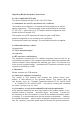
2. Pin Description
Figure 2-1. WiZ 8285 2416P Pin Connection Layout
Table 2-1. WiZ 8285 2416P pin standard definitions
Pin Number Pin Name Function Description
1
RST External reset signal (Low voltage level: Active)
2
AD ADC pin (Connected to internal WiZclick circuit)
3
EN Enable pin (Internal pull up), active high.
4
GPIO16 GPIO16 (Connected to internal WiZclick circuit)
5
GPIO14 GPIO14, PWM output for LED driver (B)
6
GPIO12 GPIO12, PWM output for LED driver (R)
7
GPIO13 GPIO13, PWM output for LED driver (CW)
8
VDD Power input for the module 3.3V
9
GND Power Ground
10
GPIO15 GPIO15 (10K internal pull-low added), PWM output for LED driver (G)
11
GPIO2 GPIO2
12
GPIO0 GPIO0
13
GPIO4 GPIO4, PWM output for LED driver (WW)
14
GPIO5 GPIO5 (or IR)
15
RXD0 UART_Rx; GPIO3
16
TXD0 UART_Tx; GPIO1
*Note: some pins function can be modified with firmware modification.
WiZ 8285 2416P User manual V19.09.1 Page 2 of 9