VERSION: 1.1 UPDATED: 9 Dec 2012 WT‐1010S GSM Alarm Panel (Alarm Backup) USER MANUAL Description The WT‐1010S GSM Alarm Panel is a wireless communicator for alarm and fire panels that uses the cell phone network (GSM) to transmit alarms and other panel event. The module checks the status of the PSTN line and in case the PSTN line becomes unavailable, the WT‐1010S GSM emulate the line signal to the panel.
General Overview WITURA CORPORATION SDN BHD | WT‐1010S GSM Alarm Panel User Manual V1.
Features Panel compatibility – Allows any contact ID alarm panel to transmit alarms over GSM using the GSM voice channel. Works over the GSM cell phone networks units can be used wherever there is cell phone coverage. Telephone line backup: WT‐1010S give priority to the lowest cost network. WT‐1010S uses the telephone line as the main transmission line and uses the GSM voice channel as backup. Auto restart system: It can continuously monitor the system status of its own.
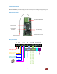
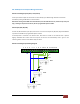
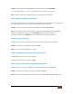
Installation Instructions Note: It is essential that you read the step by step instructions fully prior to installing and programming the unit Hardware Description Quad Band GSM Module SIM Card Holder Battery Backup Connector Time Clock Battery Terminal Blocks Connector Antenna Connector 6 7 8 9 10 11 12 13 14 15 16 GND PHONE PORT LINE PORT GND REMOTE CONTROLLING OUTPUT 1 (OUT1) ‐ GND Audible Siren Output 5 REMOTE CONTROLLING OUTPUT 2 (OUT2) Auxiliary +V Output when PSTN Failure 4 R
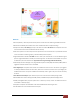
WT‐1010S Inputs and Outputs Wiring Instructions Remote Controlling Outputs (OUT1, OUT2, OUT3) These open collector outputs can be turned on or off remotely by an SMS message. Remote control will be reachable by sending an SMS with a certain command. Note: When sending normal SMS with command below, the WT‐1010S will turn On / Off the output relay and reply a message of output has turned On / Off to a programmable phone numbers.
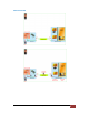
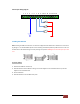
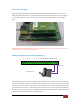
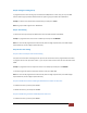
Alarm Inputs Wiring Diagram 1 2 3 4 5 6 7 8 9 10 11 12 13 14 15 16 INPUT 3 INPUT 2 INPUT 1 GND +12V Installing the SIM Card Note: Installing the SIM Card. Please be sure the initial 4 digit PIN code of SIM card is disabled. This can be done by placing it in an unlocked Mobile phone and first checking if the SIM requested any PIN code. If this is the case the PIN code can be disabled using the security settings on the phone. Warning! The WT‐1010S identifies only 3V SIM Card.
Power up the WT‐1010S When power up the WT‐1010S, the signal LED (Red) will oscillate infrequently until it finds and logs on to the Network and will then flash every 2 ‐ 3 seconds constantly and if does not happen then the unit has not logged on and it may be required to use an extension antenna or alternative network provider or re‐seat the SIM Card.
Note: Some telephone sets are sensitive to the GSM radio signal. For this reason you may hear a characteristic noise in the telephone receiver when calling. If the noise is disturbing, change the location of the phone set (try to keep it as far as possible from the WT‐1010S unit antenna). Usually it is possible to find a suitable location for the phone with minimal level of interference.
Example: To program phone number 0124857893 as Admin 1 you would press *1*0124857893# To continue program Admin 2, 3, 4, 5, 6, 7 or 8 simple press *2*, *3*, *4*, *5*, *6*, *7* or *8* Note: To delete an administrator number simply press # with entering any phone numbers Step 4: Enable the Recipient for Alert Message The unit can send text alerts to 1 or all 8 of the programmed administrator’s numbers.
Step 8: Setting the Calling Group To program the unit to dial a certain group of numbers for PSTN/AC failure or Auto Test, you can press *29* and then enter the group number of administrator the system is going to call after that ended with #. Example: To set the unit to dial the first 5 administrator you would press *29*5# Note: The group number ranges from 1 – 8. Default: 1 Step 9: Time Setting To set the time clock, you would press *16* and then enter the time after that ended with #.
To disable this function, you would press *28*0# Step 11: PSTN Failure Setting The system has the function of sending the SMS alert message, call the administrator numbers, generate a pulse (+V) or sound the audible siren when PSTN failure. To program this setting, you would press *30* and then enter the enable command after that ended with #.
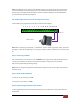
Auxiliary Power Down Output Facility on Terminal 3 In additional to the alarm and text alert on AC power failure the system also has a second permanent +V output continuously supplied from the battery backup on Terminal 3 output of the unit which will remain available for the period of AC unavailable. This power down output facility can be used to trigger an alarm on other alarm panel for alert notification.
Description: First 2 digits stands for no network time range from 00 – 59 seconds. Default: 6 seconds. Last 2 digits stands for the stay on time of Relay 2 when no network (00 – 59 seconds), 00 means RLY2 will stay ON permanently. Step 14: Input Settings The system has the function of sending the SMS alert message, call the administrator numbers or sound the audible siren when Input triggered.
To acknowledge the above alarms simply press # key on your phone and the system will stop calling you. Step 16: Setting the Automatic Call Answering Feature The WT‐1010S can be programmed to answer all incoming calls automatically. When the call is answered, it allows the owner to arm or disarm the system by entering a command from their phone’s keypad.
Step 19: Enable/Disable System Power Up SMS Notification The system is able to generate SMS notification whenever the WT‐1010S is turned on. To enable this function, you can press *46*1# To disable this function, you can press *46*0# Step 20: Enable/Disable System Armed SMS Notification The system is able to generate SMS notification whenever user armed the WT‐1010S.
Example: To set the unit to ignore the first 2 dialing digits you would press *44*2# Note: The value is 0 – 4 (Default: 0) Step 24: Changing the Program Mode Password To change the Program Mode password, you would press *0* and then enter the new 6 digits password after that ended with #.
WT‐1010S Programming Instruction (Via SMS) Programming the WT‐1010S can also be done via SMS commands using your phone. Any programming command sent by SMS must be in CAPITAL letters. The fields between square brackets are parameters; do NOT enter the square brackets. Note: Before sending SMS command to the unit, you must program your phone number into the administrator list using the fixed line phone. This is because the WT‐1010S only recognizes phone number that is in the administrator list. 1.
Note: For Contact‐ID Protocol details please refer to www.smartelectron.ru/files/DC‐05_Contact_ID.pdf 3. Editing the Message Content of Auto Test Report The message contents can be edited and programmed up to 50 characters. You can change the displayed text by sending the following commands by SMS message to the unit. Note: Only support normal abc/ABC English text, no special characters.
5. Editing the Input Alert Message (Input Restored) The Input Alert Message can be edited and programmed up to 50 characters. You can change the displayed text by sending the following commands by SMS message to the unit. Note: Only support normal abc/ABC English text, no special characters.
6.2 Activate Output Relay to Stay On Indefinitely To activate the output relay to stay on indefinitely, you can send the following text command via SMS to the unit. Text Command: *RLY[N]#ON N stands for Output number 1 ‐ 3 For example, assume that you want output relay number 1 to stay on indefinitely, you would send the following SMS message to the unit. *RLY1#ON To switch off the output relay, you can send the following text command via SMS to the unit.
Return Message DISARM 8. Checking the Signal Strength To check the signal strength of the unit, you can send the following SMS command to the unit. Text Command: *CSQ?# Example of Return Message CSQ=<28> 9. Checking the Current Time Status To check the current time, you can send the following SMS command to the unit. Text Command: *ASTM# Example of Return Message TIME‐01:35:50 10. Changing the Program Mode Password It is possible to change the login password by sending the following SMS command.
11. Reset the WT‐1010S Unit To reset the unit, you can send the following command by SMS to the unit. Text Command: *REST#XXXXXX XXXXXX stands for 6 digits password based on *PAWO# (Default: 123456) and it can be changed anytime. Technical Specifications 1. Environment temperature: 0~+50℃ 2. Relative humidity: 10%~95% 3. Air pressure: 86~106kpa 4. Environment yawp: ≤60dB (A) 5. Working frequency: GSM850MHz/900MHz/1800MHz/1900MHz/2100MHz 6. Stability of frequency: better than 2.5PPM 7.
Warranty Witura Corporation Sdn Bhd guarantees all WT‐1010S GSM Fixed Wireless Terminal against defective parts and workmanship. Witura Corporation Sdn Bhd shall, at its option, repair or replace the defective equipment upon the return of such equipment to any Witura branch.