
Specification Sheet
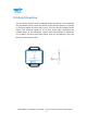
Table Of Contents
- Tutorial Link
- Contact
- Application
- Contents
- 2 Features
- 3 Specification
- 5 Casing Specification
- 6 Communication Protocol
- 6.1 Output Data Format
- 6.2 Config Commands
- 6.2.1 Register Address
- 6.2.2 Save Configuration
- 6.2.3 Calibrate
- 6.2.4 Installation Direction
- 6.2.5 Sleep/ Wake up
- 6.2.6 Algorithm Transition
- 6.2.7 Gyroscope Automatic Calibration
- 6.2.8 Return Content
- 6.2.9 Return Rate
- 6.2.10 Baud Rate
- 6.2.11 Set X Axis Acceleration Bias
- 6.2.12 Set Y Axis Acceleration Bias
- 6.2.13 Set Z Axis Acceleration Bias
- 6. 2.14 Set X Axis Angular Velocity Bias
- 6.2.15 Set Y Axis Angular Velocity Bias
- 5.2.16 Set Z Axis Angular Velocity Bias
- 6.2.17 Set X Axis Magnetic Bias
- 6.2.18 Set Y Axis Magnetic Bias
- 6.2.19 Set Z Axis Magnetic Bias

WT901SDCL | Datasheet v20-0605 | http://wiki.wit-motion.com/english
- 10 -
3.3 Axial Direction
The coordinate system used for attitude angle settlement is the northeast
sky coordinate system. Place the module in the positive direction, as shown
in the figure below, direction left is the Y-axis, the direction forward is the
X-axis, and direction upward is the Z-axis. Euler angle represents the
rotation order of the coordinate system when the attitude is defined as
Z-Y-X, that is, first turn around the Z-axis, then turn around the Y-axis, and
then turn around the X-axis.