WitMotion Shenzhen Co., Ltd| Datasheet AHRS IMU Sensor | WTGAHRS2 The Robust Acceleration, Angular velocity, Angle , Magnetic filed & Air Pressure & GPS Monitor Detector The WTGAHRS2 is a IMU sensor device, detecting acceleration, angular velocity, angle , magnetic filed , air pressure as well as gps data. The robust housing and the small outline makes it perfectly suitable for industrial applications such as condition monitoring and predictive maintenance.
Tutorial Link Google Drive Link to instructions DEMO: WITMOTION Youtube Channel WTGAHRS2 Playlist If you have technical problems or cannot find the information that you need in the provided documents, please contact our support team. Our engineering team is committed to providing the required support necessary to ensure that you are successful with the operation of our AHRS sensors.
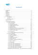
Contents Tutorial Link............................................................................................................................. - 2 Contact....................................................................................................................................... - 2 Application................................................................................................................................ - 2 Contents.............................................................
5.2.16 5.2.17 5.2.18 5.2.19 5.2.20 Set Set Set Set Set Z Axis Angular Velocity Bias.................................................... X Axis Magnetic Bias................................................................... Y Axis Magnetic Bias................................................................... Z Axis Magnetic Bias................................................................... GPS baud.........................................................................................
1 Overview WTGAHRS2’s scientific name is AHRS IMU sensor. A sensor measures 3-axis angle, angular velocity, acceleration, magnetic field, air pressure and GPS data. Its strength lies in the algorithm which can calculate three-axis angle accurately. WTGAHRS2 is employed where the highest measurement accuracy is required.
2 Features Built-in WT901B + GPS + BeiDou module, for detailed parameters, please refer to the instructions of WT901B. The default baud rate of this device is 9600 and could be changed. The interface of this product only leads to a serial port The module consists of a high precision gyroscope, accelerometer, geomagnetic field and barometer sensor.
3 Specification 3.1 Parameter Parameter Specification Working Voltage TTL:3.3V-5V Current <40mA Size 61.2mm x 45.2mm X 27.8mm Data Angle: X Y Z, 3-axis Acceleration: X Y Z, 3-axis Angular Velocity: X Y Z, 3-axis Magnetic Field : X Y Z, 3-axis Air Pressure : 1-Axis Positioning (longitude, latitude) Ground speed Number of satellites Time, Quaternion Output frequency 0.
Measurement Range & Accuracy Sensor Measurement Range Accuracy/ Remark Accelerometer X, Y, Z, 3-axis ±16g Accuracy: 0.01g Resolution: 16bit Stability: 0.005g Gyroscope X, Y, Z, 3-axis -±2000°/s Resolution: 16bit Stability: 0.05°/s Magnetometer X, Y, Z, 3-axis ±4900µT 0.15µT/LSB typ. (16-bit) AK8963 Magnetometer Chip Angle/ Inclinometer X, Y, Z, 3-axis X, Z-axis: ±180° Y ±90° (Y-axis 90° is singular point) Accuracy:X, Y-axis: 0.
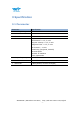
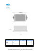
3.2 Size Parameter Specification Tolerance Length 80 ±0.1 Width 45 ±0.1 Height 28 ±0.1 Weight 50 ±1 WTGAHRS2 | Datasheet v20-0523 | Comment Unit: millimeter. Unit: gram http://wiki.wit-motion.
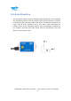
3.3 Axial Direction The coordinate system used for attitude angle settlement is the northeast sky coordinate system. Place the module in the positive direction, as shown in the figure below, direction right is the X-axis, the direction forward is the Y-axis, and direction upward is the Z-axis. Euler angle represents the rotation order of the coordinate system when the attitude is defined as Z-Y-X, that is, first turn around the Z-axis, then turn around the Y-axis, and then turn around the X-axis.
4 PIN Definition PIN Color Function VCC RED Input Supply TTL : powered by 3.3-5V RX GREEN Serial data input RX connected with TX TX YELLOW Serial data output TX RX connected with RX GND BLACK Ground GND WTGAHRS2 | Datasheet v20-0523 | http://wiki.wit-motion.
5 Communication Protocol Level: TTL level Baud rate: 4800, 9600 (default), 19200 38400, 57600, 115200, 230400, 460800, 921600, stop bit and parity 5.1 Output Data Format 5.1.1 Time Output 0x55 0x50 YY MM DD hh mm ss msL msH SUM YY:Year, 20YY Year MM:Month DD:Day hh:hour mm:minute ss:Second ms:Millisecond Millisecond calculate formula: ms=((msH<<8)|msL) Sum=0x55+0x51+YY+MM+DD+hh+mm+ss+ms+TL WTGAHRS2 | Datasheet v20-0523 | http://wiki.wit-motion.
5.1.2 Acceleration Output 0x55 0x51 AxL AxH AyL AyH AzL AzH TL TH SUM Calculate formula: ax=((AxH<<8)|AxL)/32768*16g(g is Gravity acceleration, 9.8m/s2) ay=((AyH<<8)|AyL)/32768*16g(g is Gravity acceleration, 9.8m/s2) az=((AzH<<8)|AzL)/32768*16g(g is Gravity acceleration, 9.8m/s2) Temperature calculated formular: T=((TH<<8)|TL)/100 ℃ Checksum: Sum=0x55+0x51+AxH+AxL+AyH+AyL+AzH+AzL+TH+TL Note: 1. The data is sent in hexadecimal, not ASCII code.
5.1.4 Angle Output 0x55 0x53 RollL RollH PitchL PitchH YawL YawH VL VH SUM Calculated formular: Roll(X axis)Roll=((RollH<<8)|RollL)/32768*180(°) Pitch(Y axis)Pitch=((PitchH<<8)|PitchL)/32768*180(°) Yaw(Z axis)Yaw=((YawH<<8)|YawL)/32768*180(°) Version calculated formula: Version=(VH<<8)|VL Checksum: Sum=0x55+0x53+RollH+RollL+PitchH+PitchL+YawH+YawL+VH+VL Note: 1. The coordinate system used for attitude angle settlement is the northeast sky coordinate system.
5.1.5 Magnetic Output 0x55 0x54 HxL HxH HyL HyH HzL HzH TL TH SUM Calculated formular: Magnetic(x axis)Hx=(( HxH<<8)| HxL) Magnetic(y axis)Hy=(( HyH <<8)| HyL) Magnetic(z axis)Hz =(( HzH<<8)| HzL) Temperature calculated formular: T=((TH<<8)|TL) /100℃ Checksum: Sum=0x55+0x53+HxH+HxL+HyH+HyL+HzH+HzL+TH+TL 5.1.
5.1.7 Longitude and Latitude Output 0x55 0x57 Lon0 Lon 1 Lon 2 Lon 3 Lat0 Lat 1 Lat 2 Lat 3 SUM Calculated formular: Longitude Lon = ((Lon 3<<24)| (Lon 2<<16)| (Lon 1<<8)| Lon 0 In NMEA0183 standard , GPS output format is ddmm.mmmmm (dd for the degree, mm.mmmmm is after decimal point ), the module removes the decimal point during output, so the degree of longitude can be calculated as follows: dd=Lon/100000000; mm.
5.1.9 Quaternion 0x55 0x59 Q0L Q0H Q1L Q1H Q2L Q2H Q3L Q3H SUM Calculated formular: Q0=((Q0H<<8)|Q0L)/32768 Q1=((Q1H<<8)|Q1L)/32768 Q2=((Q2H<<8)|Q2L)/32768 Q3=((Q3H<<8)|Q3L)/32768 Checksum: Sum=0x55+0x59+Q0L+Q0H+Q1L +Q1H +Q2L+Q2H+Q3L+Q3H 5.1.
5.2 Config Commands Reminder: 1. Data format 0xFF 0xAA Address DataL DataH 5.2.
0x3b HY Y axis Magnetic 0x3c HZ Z axis Magnetic 0x3d Roll X axis Angle 0x3e Pitch Y axis Angle 0x3f Yaw Z axis Angle 0x40 TEMP Temperature 0x41~0x44 RSV D0Status 0x45 PressureL Pressure Low Byte 0x46 PressureH Pressure High Byte 0x47 HeightL Height Low Byte 0x48 HeightH Height High Byte 0x49 LonL Longitude Low Byte 0x4a LonH Longitude High Byte 0x4b LatL Latitude Low Byte 0x4c LatH Latitude High Byte 0x4d GPSHeight GPS Height 0x4e GPSYaw GPS Yaw 0x4f GPSVL
5.2.2 Save Configuration 0xFF 0xAA 0x00 SAVE 0x00 CALSW 0x00 SAVE:Save 0:Save current configuration 1:set to default setting 5.2.3 Calibrate 0xFF 0xAA 0x01 CALSW:Set calibration mode 0:Exit calibration mode 1:Enter Gyroscope and Accelerometer calibration mode 2:Enter magnetic calibration mode 3:Set height to 0 5.2.4 Installation Direction 0xFF 0xAA 0x23 DIRECTION 0x00 DIRECTION:set installation direction 0:set to horizontal installation 1:set to vertical installation 5.2.
5.2.6 Algorithm Transition 0xFF 0xAA 0x24 ALG 0x00 ALG:6-axis/ 9-axis algorithm transition 0:switch to 9-axis algorithm 1:switch to 6-axis algorithm 5.2.7 Gyroscope Automatic Calibration 0xFF 0xAA 0x63 GYRO 0x00 GYRO:gyroscope automatic calibration 0:set to gyroscope automatic calibration 1:removed to gyroscope automatic calibration WTGAHRS2 | Datasheet v20-0523 | http://wiki.wit-motion.
5.2.8 Return Content 0xFF 0xAA RSWL byte definition byte 7 6 0x02 5 RSWL 4 RSWH 3 2 1 0 Name 0x57 pack 0x56 pack 0x55 pack 0x54 pack 0x53 pack 0x52 pack 0x51 pack 0x50 pack default 0 0 0 1 1 1 1 0 RSWH byte definition byte 7 6 5 4 3 2 1 0 Name X X X X X 0x5A pack 0x59 pack 0x58 pack default 0 0 0 0 0 0 0 0 X is an undefined value.
0:Not output 0x57 pack 1:Output 0x57 pack 0x58 pack:GPS speed Pack 0:Not output 0x58 pack 1:Output 0x58 pack 0x59 pack:Quaternion Pack 0:Not output 0x59 pack 1:Output 0x59 pack 0x5A pack:Satellite position accuracy 0:Not output 0x5A pack 1:Output 0x5A pack WTGAHRS2 | Datasheet v20-0523 | http://wiki.wit-motion.
5.2.9 Return Rate 0xFF 0xAA 0x03 RATE 0x00 RATE:return rate 0x01 :0.2Hz 0x02:0.5Hz 0x03:1Hz 0x04:2Hz 0x05:5Hz 0x06:10Hz(default) 0x07:20Hz 0x08:50Hz 0x09:100Hz 0x0a:125Hz 0x0b:200Hz 0x0c:Single 0x0d: Not output After the setup is complete, need to click save, and re-power the module to take effect. Eg(20Hz of Return Rate): 1. FF AA 69 88 B5(Unlock) 2. FF AA 03 07 00(20HZ) 3.FF AA 00 00 00(Save Config) 5.2.
5.2.11 Set X Axis Acceleration Bias 0xFF 0xAA 0x05 AXOFFSETL AXOFFSETH AXOFFSETL:X axis Acceleration bias low byte AXOFFSETH:X axis Acceleration bias high byte AXOFFSET= (AXOFFSETH <<8) | AXOFFSETL Note:After setting the acceleration bias, the output value of the acceleration is the sensor measured value minus the bias value. 5.2.
5.2.14 Set X Axis Angular Velocity Bias 0xFF 0xAA 0x08 GXOFFSETL GXOFFSETH GXOFFSETL:Set X axis Angular velocity bias low byte GXOFFSETH:Set Y axis Angular velocity bias high byte GXOFFSET= (GXOFFSETH <<8) | GXOFFSETL Note:After setting the angular velocity zero deviation, the output value of the angular velocity is the sensor measurement value minus the zero deviation value. 5.2.
5.2.17 Set X Axis Magnetic Bias 0xFF 0xAA 0x0b HXOFFSETL HXOFFSETH HXOFFSETL:Set X axis magnetic bias low byte HXOFFSETH:Set X axis magnetic bias high byte HXOFFSET= (HXOFFSETH <<8) | HXOFFSETL Note:After setting the magnetic field bias, the output value of the magnetic field is the sensor measured value minus the zero bias value. 5.2.
5.2.20 Set GPS baud 0xFF 0xAA 0x1c GPSBAUD 0x00 GPSBAUD: Baud: Time information pack 0x00:2400 0x01:4800 0x02:9600(default) 0x03:19200 0x04:38400 0x05:57600 0x06:115200 0x07:230400 0x08:460800 0x09:921600 After set it up, you need to save the configuration button, Click “Save Config”button and then restart the module. WTGAHRS2 | Datasheet v20-0523 | http://wiki.wit-motion.