
Specification Sheet
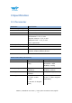
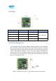
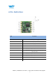
Table Of Contents
- Tutorial Link
- Contact
- Application
- Contents
- 1 Overview
- 2 Features
- 3 Specification
- 4 Pin Definition
- 5 Communication Protocol
- 5.2 Config Commands
- 5.2.1 Register Address
- 5.2.2 Save Configuration
- 5.2.3 Calibrate
- 5.2.4 Installation Direction
- 5.2.5 Sleep/ Wake up
- 5.2.6 Algorithm Transition
- 5.2.7 Gyroscope Automatic Calibration
- 5.2.8 Return Content
- 5.2.9 Return Rate
- 5.2.10 Baud Rate
- 5.2.11 Set X Axis Acceleration Bias
- 5.2.12 Set Y Axis Acceleration Bias
- 5.2.13 Set Z Axis Acceleration Bias
- 5.2.14 Set X Axis Angular Velocity Bias
- 5.2.15 Set Y Axis Angular Velocity Bias
- 5.2.16 Set Z Axis Angular Velocity Bias
- 5.2.17 Set X Axis Magnetic Bias
- 5.2.18 Set Y Axis Magnetic Bias
- 5.2.19 Set Z Axis Magnetic Bias
- 5.2.20 Set port D0 mode
- 5.2.21 Set port D1 mode
- 5.2.22 Set port D2 mode
- 5.2.23 Set port D3 mode
- 5.2.24 Set the PWM width of Port D0
- 5.2.25 Set the PWM width of Port D1
- 5.2.26 Set the PWM width of Port D2
- 5.2.27 Set the PWM width of Port D3
- 5.2.28 Set period of Port D0
- 5.2.29 Set period of Port D1
- 5.2.30 Set period of Port D2
- 5.2.31 Set period of Port D3
- 5.2.32 Set IIC Address
- 5.2.33 LED
- 5.2.34 Set GPS baud
- 5.2.35Set alarm of module
- 6 IIC Protocol

WT901 | Datasheet v20-0702 | http://wiki.wit-motion.com/english
- 8 -
3.2 Size
Parameter
Specification
Tolerance
Comment
Length
15
±0.1
Unit: millimeter.
Width
15
±0.1
Height
2
±0.1
Weight
1
±0.1
Unit: gram
3.3 Axial Direction
The coordinate system used for attitude angle settlement is the northeast
sky coordinate system. Place the module in the positive direction, as shown
in the figure below, direction right is the X-axis, the direction forward is the
Y-axis, and direction upward is the Z-axis. Euler angle represents the
rotation order of the coordinate system when the attitude is defined as
Z-Y-X, that is, first turn around the Z-axis, then turn around the Y-axis, and
then turn around the X-axis.