
Specification Sheet
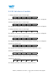
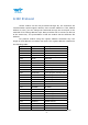
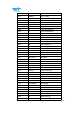
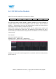
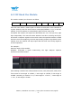
Table Of Contents
- Tutorial Link
- Contact
- Application
- Contents
- 1 Overview
- 2 Features
- 3 Specification
- 4 Pin Definition
- 5 Communication Protocol
- 5.2 Config Commands
- 5.2.1 Register Address
- 5.2.2 Save Configuration
- 5.2.3 Calibrate
- 5.2.4 Installation Direction
- 5.2.5 Sleep/ Wake up
- 5.2.6 Algorithm Transition
- 5.2.7 Gyroscope Automatic Calibration
- 5.2.8 Return Content
- 5.2.9 Return Rate
- 5.2.10 Baud Rate
- 5.2.11 Set X Axis Acceleration Bias
- 5.2.12 Set Y Axis Acceleration Bias
- 5.2.13 Set Z Axis Acceleration Bias
- 5.2.14 Set X Axis Angular Velocity Bias
- 5.2.15 Set Y Axis Angular Velocity Bias
- 5.2.16 Set Z Axis Angular Velocity Bias
- 5.2.17 Set X Axis Magnetic Bias
- 5.2.18 Set Y Axis Magnetic Bias
- 5.2.19 Set Z Axis Magnetic Bias
- 5.2.20 Set port D0 mode
- 5.2.21 Set port D1 mode
- 5.2.22 Set port D2 mode
- 5.2.23 Set port D3 mode
- 5.2.24 Set the PWM width of Port D0
- 5.2.25 Set the PWM width of Port D1
- 5.2.26 Set the PWM width of Port D2
- 5.2.27 Set the PWM width of Port D3
- 5.2.28 Set period of Port D0
- 5.2.29 Set period of Port D1
- 5.2.30 Set period of Port D2
- 5.2.31 Set period of Port D3
- 5.2.32 Set IIC Address
- 5.2.33 LED
- 5.2.34 Set GPS baud
- 5.2.35Set alarm of module
- 6 IIC Protocol

WT901 | Datasheet v20-0702 | http://wiki.wit-motion.com/english
- 37 -
6.1 IIC Write the Module
When IIC write the module, the format is as below:
IICAddr<<1
RegAddr
Data1L
Data1H
Data2L
Data2H
……
First IIC host sends a Start signal to WT901 module, then write IICAddr to
register address and then write RegAddr, write the Data1L Data1H Data2L
Data2H …. Sequentially, when the last data has been written, the host sends a
stop signal to the module to release the IIC bus.
When finish writing the data, the register will be updated and module will
execute the order.At the same time, the address of the module will add 1
automatically.The address Pointer will point to next address. So it can be written
Continuously.
For example:
Set D0 as Digital output high
RegAddr :0x0e DataL:0x02 DataH:0x00
Logic Analyzer captures waveforms as shown below:
Register set up by the module approach is consistent with the serial protocol,
please refer 6.1