
Specification Sheet
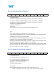
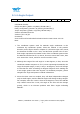
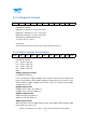
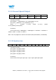
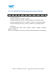
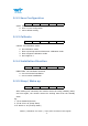
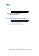
Table Of Contents
- Tutorial Link
- Contact
- Application
- Contents
- 1 Overview
- 2 Features
- 3 Specification
- 4 Pin Definition
- 5 Communication Protocol
- 5.2 Config Commands
- 5.2.1 Register Address
- 5.2.2 Save Configuration
- 5.2.3 Calibrate
- 5.2.4 Installation Direction
- 5.2.5 Sleep/ Wake up
- 5.2.6 Algorithm Transition
- 5.2.7 Gyroscope Automatic Calibration
- 5.2.8 Return Content
- 5.2.9 Return Rate
- 5.2.10 Baud Rate
- 5.2.11 Set X Axis Acceleration Bias
- 5.2.12 Set Y Axis Acceleration Bias
- 5.2.13 Set Z Axis Acceleration Bias
- 5.2.14 Set X Axis Angular Velocity Bias
- 5.2.15 Set Y Axis Angular Velocity Bias
- 5.2.16 Set Z Axis Angular Velocity Bias
- 5.2.17 Set X Axis Magnetic Bias
- 5.2.18 Set Y Axis Magnetic Bias
- 5.2.19 Set Z Axis Magnetic Bias
- 5.2.20 Set port D0 mode
- 5.2.21 Set port D1 mode
- 5.2.22 Set port D2 mode
- 5.2.23 Set port D3 mode
- 5.2.24 Set the PWM width of Port D0
- 5.2.25 Set the PWM width of Port D1
- 5.2.26 Set the PWM width of Port D2
- 5.2.27 Set the PWM width of Port D3
- 5.2.28 Set period of Port D0
- 5.2.29 Set period of Port D1
- 5.2.30 Set period of Port D2
- 5.2.31 Set period of Port D3
- 5.2.32 Set IIC Address
- 5.2.33 LED
- 5.2.34 Set GPS baud
- 5.2.35Set alarm of module
- 6 IIC Protocol

WT901 | Datasheet v20-0702 | http://wiki.wit-motion.com/english
- 13 -
5.1.5 Magnetic Output
0x55
0x54
HxL
HxH
HyL
HyH
HzL
HzH
TL
TH
SUM
Calculated formula:
Magnetic(x axis)Hx=(( HxH<<8)| HxL)
Magnetic(y axis)Hy=(( HyH <<8)| HyL)
Magnetic(z axis)Hz =(( HzH<<8)| HzL)
Temperature calculated formula:
T=((TH<<8)|TL) /100℃
Checksum:
Sum=0x55+0x53+HxH+HxL+HyH+HyL+HzH+HzL+TH+TL
5.1.6 Data Output Port Status
0x55
0x55
D0L
D0H
D1L
D1H
D2L
D2H
D3L
D3H
SUM
Calculated formula:
D0 = (D0H<<8)| D0L
D1 = (D1H<<8)| D1L
D2 = (D2H<<8)| D2L
D3 = (D3H<<8)| D3L
Note:
Analog input port mode:
U=DxStatus/1024*U
vcc
Uvcc is the power supply voltage of the module, because the module has
LDO, if the module power supply voltage is greater than 3.5V, Uvcc is 3.3V.
If the module supply voltage is less than 3.5V, Uvcc equal to the supply
voltage minus 0.2V
Digital input mode:
Voltage level is high, the data is 1,
Voltage level is low, the data is 0.
Digital output mode:
Output is high, the data is 1.
Output is low, the data is 0.
PWM output mode:
When the port is set to PWM output mode, port status data indicates high
level width, the unit is “us”.