WitMotion Shenzhen Co., Ltd| Datasheet AHRS IMU Sensor | WT901 The Robust Acceleration, Angular velocity, Angle & Magnetic filed Detector The WT901 is a IMU sensor device, detecting acceleration, angular velocity, angle as well as magnetic filed. The robust housing and the small outline makes it perfectly suitable for industrial applications such as condition monitoring and predictive maintenance.
Tutorial Link Google Drive Link to instructions DEMO: WITMOTION Youtube Channel WT901 Playlist If you have technical problems or cannot find the information that you need in the provided documents, please contact our support team. Our engineering team is committed to providing the required support necessary to ensure that you are successful with the operation of our AHRS sensors.
Contents Tutorial Link............................................................................................................................. - 2 Contact....................................................................................................................................... - 2 Application................................................................................................................................ - 2 Contents.............................................................
5.2.14 Set X Axis Angular Velocity Bias.................................................... 5.2.15 Set Y Axis Angular Velocity Bias.................................................... 5.2.16 Set Z Axis Angular Velocity Bias.................................................... 5.2.17 Set X Axis Magnetic Bias................................................................... 5.2.18 Set Y Axis Magnetic Bias................................................................... 5.2.19 Set Z Axis Magnetic Bias.......
1 Overview WT901’s scientific name is AHRS IMU sensor. A sensor measures 3-axis angle, angular velocity, acceleration, magnetic field. Its strength lies in the algorithm which can calculate three-axis angle accurately. WT901 is employed where the highest measurement accuracy is required.
2 Features The default baud rate of this device is 9600 and could be changed. The interface of this product only leads to a serial port The module consists of a high precision gyroscope, accelerometer and geomagnetic field sensor. The product can solve the current real-time motion posture of the module quickly by using the high-performance microprocessor, advanced dynamic solutions and Kalman filter algorithm.
3 Specification 3.1 Parameter Parameter Specification Working Voltage 3.3V-5V Current <25mA Size 15mm x 15mm X 2mm Data Angle: X Y Z, 3-axis Acceleration: X Y Z, 3-axis Angular Velocity: X Y Z, 3-axis Magnetic Field : X Y Z, 3-axis Time, Quaternion Output frequency 0.
3.2 Size Parameter Specification Tolerance Length 15 ±0.1 Width 15 ±0.1 Height 2 ±0.1 Weight 1 ±0.1 Comment Unit: millimeter. Unit: gram 3.3 Axial Direction The coordinate system used for attitude angle settlement is the northeast sky coordinate system. Place the module in the positive direction, as shown in the figure below, direction right is the X-axis, the direction forward is the Y-axis, and direction upward is the Z-axis.
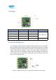
4 Pin Definition PIN Function VCC 3.3-5V input supply RX Serial data input, TTL interface TX Serial data output, TTL interface GND DO Analog input, digital input and output, PWM D1 Analog input, digital input and output, PWM, connect GPS D2 Analog input, digital input and output, PWM D3 Analog input, digital input and output, PWM SDA I2C signal line SCL I2C clock line Ground WT901 | Datasheet v20-0702 | http://wiki.wit-motion.
5 Communication Protocol Level: TTL level Baud rate:4800, 9600 (default), 19200 38400, 57600, 115200, 230400, 460800, 921600, stop bit and parity 5.1 Output Data Format 5.1.1 Time Output 0x55 0x50 YY MM DD hh mm ss msL msH SUM YY:Year, 20YY Year MM:Month DD:Day hh:hour mm:minute ss:Second ms:Millisecond Millisecond calculate formula: ms=((msH<<8)|msL) Sum=0x55+0x51+YY+MM+DD+hh+mm+ss+ms+TL WT901 | Datasheet v20-0702 | http://wiki.wit-motion.
5.1.2 Acceleration Output 0x55 0x51 AxL AxH AyL AyH AzL AzH TL TH SUM Calculate formula: ax=((AxH<<8)|AxL)/32768*16g(g is Gravity acceleration, 9.8m/s2) ay=((AyH<<8)|AyL)/32768*16g(g is Gravity acceleration, 9.8m/s2) az=((AzH<<8)|AzL)/32768*16g(g is Gravity acceleration, 9.8m/s2) Temperature calculated formula: T=((TH<<8)|TL)/100 ℃ Checksum: Sum=0x55+0x51+AxH+AxL+AyH+AyL+AzH+AzL+TH+TL Note: 1. The data is sent in hexadecimal, not ASCII code.
5.1.4 Angle Output 0x55 0x53 RollL RollH PitchL PitchH YawL YawH VL VH SUM Calculated formula: Roll(X axis)Roll=((RollH<<8)|RollL)/32768*180(°) Pitch(Y axis)Pitch=((PitchH<<8)|PitchL)/32768*180(°) Yaw(Z axis)Yaw=((YawH<<8)|YawL)/32768*180(°) Version calculated formula: Version=(VH<<8)|VL Checksum: Sum=0x55+0x53+RollH+RollL+PitchH+PitchL+YawH+YawL+VH+VL Note: 1. The coordinate system used for attitude angle settlement is the northeast sky coordinate system.
5.1.5 Magnetic Output 0x55 0x54 HxL HxH HyL HyH HzL HzH TL TH SUM D3H SUM Calculated formula: Magnetic(x axis)Hx=(( HxH<<8)| HxL) Magnetic(y axis)Hy=(( HyH <<8)| HyL) Magnetic(z axis)Hz =(( HzH<<8)| HzL) Temperature calculated formula: T=((TH<<8)|TL) /100℃ Checksum: Sum=0x55+0x53+HxH+HxL+HyH+HyL+HzH+HzL+TH+TL 5.1.
5.1.7 Atmospheric Pressure and Height Output 0x55 0x56 P0 P1 P2 P3 H0 H1 H2 H3 SUM Calculated formula: Atmospheric pressure P = (( P3<<24)| ( P2<<16)| ( P1<<8)| P0 (Pa) Height H = (( H3<<24)| ( H2<<16)| ( H1<<8)| H0(cm) Checksum: Sum=0x55+0x54+P0+P1+P2+P3+H0+H1+H2+H3 Note:This only applies to devices with barometer(WT901B, HWT901B, BWT901BCL, WTGAHRS1, WTGAHRS2) 5.1.
5.1.9 Ground Speed Output 0x55 0x58 GPSHeightL GPSHeightH GPSYawL GPSV0 GPSV 1 GPSV 2 GPSV 3 SUM GPSYawH Calculated formula: GPS Height= ((GPSHeightH<<8)| GPSHeightL)/10 (m) GPS Yaw=( (GPSYawH <<8)| GPSYawL)/10 (°) GPSV = (((GPSV 3<<24)| (GPSV 2<<16)| 2<<8)|GPSV0)/1000(km/h) (GPSV Checksum: Sum=0x55+0x54+ GPSHeightL + GPSHeightH + GPSYawL + GPSYawH + GPSV0+ GPSV 1+ GPSV 2+ GPSV 3 Note: This only applies to devices with GPS module(WTGAHRS1, WTGAHRS2) 5.1.
5.1.
5.2 Config Commands Reminder: 1. Data format 0xFF 0xAA Address DataL DataH 5.2.
0x1c GPSBAUD GPS baud rate 0x30 MMYY Month , Year 0x31 HHDD Hour , Day 0x32 SSMM Second , Minute 0x33 MS Millisecond 0x34 AX X axis Acceleration 0x35 AY Y axis Acceleration 0x36 AZ Z axis Acceleration 0x37 GX X axis angular velocity 0x38 GY Y axis angular velocity 0x39 GZ Z axis angular velocity 0x3a HX X axis Magnetic 0x3b HY Y axis Magnetic 0x3c HZ Z axis Magnetic 0x3d Roll X axis Angle 0x3e Pitch Y axis Angle 0x3f Yaw Z axis Angle 0x40 TEMP Temperature
5.2.2 Save Configuration 0xFF 0xAA 0x00 SAVE 0x00 CALSW 0x00 SAVE:Save 0:Save current configuration 1:set to default setting 5.2.3 Calibrate 0xFF 0xAA 0x01 CALSW:Set calibration mode 0:Exit calibration mode 1:Enter Gyroscope and Accelerometer calibration mode 2:Enter magnetic calibration mode 3:Set height to 0 5.2.4 Installation Direction 0xFF 0xAA 0x23 DIRECTION 0x00 DIRECTION:set installation direction 0:set to horizontal installation 1:set to vertical installation 5.2.
5.2.6 Algorithm Transition 0xFF 0xAA 0x24 ALG 0x00 ALG:6-axis/ 9-axis algorithm transition 0:switch to 9-axis algorithm 1:switch to 6-axis algorithm 5.2.7 Gyroscope Automatic Calibration 0xFF 0xAA 0x63 GYRO 0x00 GYRO:gyroscope automatic calibration 0:set to gyroscope automatic calibration 1:removed to gyroscope automatic calibration WT901 | Datasheet v20-0702 | http://wiki.wit-motion.
5.2.8 Return Content 0xFF 0xAA RSWL byte definition byte 7 6 0x02 5 RSWL 4 RSWH 3 2 1 0 Name 0x57 pack 0x56 pack 0x55 pack 0x54 pack 0x53 pack 0x52 pack 0x51 pack 0x50 pack default 0 0 0 1 1 1 1 0 RSWH byte definition byte 7 6 5 4 3 2 1 0 Name X X X X X 0x5A pack 0x59 pack 0x58 pack default 0 0 0 0 0 0 0 0 X is an undefined value.
0:Not output 0x57 pack 1:Output 0x57 pack 0x58 pack:GPS speed Pack 0:Not output 0x58 pack 1:Output 0x58 pack 0x59 pack:Quaternion Pack 0:Not output 0x59 pack 1:Output 0x59 pack 0x5A pack:Satellite position accuracy 0:Not output 0x5A pack 1:Output 0x5A pack WT901 | Datasheet v20-0702 | http://wiki.wit-motion.
5.2.9 Return Rate 0xFF 0xAA 0x03 RATE 0x00 RATE:return rate 0x01 :0.2Hz 0x02:0.5Hz 0x03:1Hz 0x04:2Hz 0x05:5Hz 0x06:10Hz(default) 0x07:20Hz 0x08:50Hz 0x09:100Hz 0x0a:125Hz 0x0b:200Hz 0x0c:Single 0x0d: Not output After the setup is complete, need to click save, and re-power the module to take effect. Eg(20Hz of Return Rate): 1. FF AA 69 88 B5(Unlock) 2. FF AA 03 07 00(20HZ) 3.FF AA 00 00 00(Save Config) WT901 | Datasheet v20-0702 | http://wiki.wit-motion.
5.2.10 Baud Rate 0xFF 0xAA 0x04 BAUD 0x00 BAUD: 0x01:4800 0x02:9600(default) 0x03:19200 0x04:38400 0x05:57600 0x06:115200 0x07:230400 0x08:460800 0x09:921600 5.2.11 Set X Axis Acceleration Bias 0xFF 0xAA 0x05 AXOFFSETL AXOFFSETH AXOFFSETL:X axis Acceleration bias low byte AXOFFSETH:X axis Acceleration bias high byte AXOFFSET= (AXOFFSETH <<8) | AXOFFSETL Note:After setting the acceleration bias, the output value of the acceleration is the sensor measured value minus the bias value. 5.2.
5.2.13 Set Z Axis Acceleration Bias 0xFF 0xAA 0x07 AZOFFSETL AZOFFSETH AZOFFSETL:Z axis Acceleration bias low byte AZOFFSETH:Z axis Acceleration bias high byte AZOFFSET= (AZOFFSETH <<8) | AZOFFSETL Note:After setting the acceleration bias, the output value of the acceleration is the sensor measured value minus the bias value. 5.2.
5.2.16 Set Z Axis Angular Velocity Bias 0xFF 0xAA 0x0a GXOFFSETL GXOFFSETH GZOFFSETL:Set Z axis Angular velocity bias low byte GZOFFSETH:Set Z axis Angular velocity bias low byte GZOFFSET= (GZOFFSETH <<8) | GZOFFSETL Note:After setting the angular velocity zero deviation, the output value of the angular velocity is the sensor measurement value minus the zero deviation value. 5.2.
5.2.19 Set Z Axis Magnetic Bias 0xFF 0xAA 0x0d HXOFFSETL HXOFFSETH HXOFFSETL:Set Y axis magnetic bias low byte HXOFFSETH:Set Z axis magnetic bias high byte HXOFFSET= (HXOFFSETH <<8) | HXOFFSETL Note:After setting the magnetic field bias, the output value of the magnetic field is the sensor measured value minus the zero bias value. 5.2.
5.2.22 Set port D2 mode 0xFF 0xAA 0x0e D2MODE 0x00 D2MODE: 0x00:Analog Input(default) 0x01:Digital Input 0x02:Digital Output high 0x03:Digital Output low 0x04:PWM Output 5.2.23 Set port D3 mode 0xFF 0xAA 0x0e D3MODE 0x00 D3MODE: 0x00:Analog Input(default) 0x01:Digital Input 0x02:Digital Output high 0x03:Digital Output low 0x04:PWM Output 5.2.
5.2.25 Set the PWM width of Port D1 0xFF 0xAA 0x13 D1PWMHL D1PWMHH D1PWMHL:the PWM width of Port D1 low byte D1PWMHH:the PWM width of Port D1 high byte D1PWMH = (D1PWMHH<<8) | D1PWMHL Note: The unit of PWM high-level width and period is us, such as high-level width is 1500us, just set D0PWMH 1500. 5.2.
5.2.27 Set the PWM width of Port D3 0xFF 0xAA 0x15 D3PWMHL D3PWMHH D3PWMHL:the PWM width of Port D3 low byte D3PWMHH:the PWM width of Port D3 low byte D3PWMH = (D3PWMHH<<8) | D3PWMHL Note: The unit of PWM high-level width and period is us, such as high-level width is 1500us, just set D0PWMH 1500. 5.2.
5.2.29 Set period of Port D1 0xFF 0xAA 0x17 D1PWMTL D1PWMTH D1PWMTL:PWM period of Port D1 low byte D1PWMTH:PWM period of Port D1 high byte D1PWMT = (D1PWMTH<<8) | D1PWMTL Note: The unit of PWM high-level width and period is us, such as high-level width is 1500us, just set D0PWMH 1500.Period is 20000us, just set D0PWMT 20000. 5.2.
5.2.31 Set period of Port D3 0xFF 0xAA 0x19 D3PWMTL D3PWMTH D3PWMTL:PWM period of Port D3 low byte D3PWMTH:PWM period of Port D3 high byte D3PWMT = (D3PWMTH<<8) | D3PWMTL Note: The unit of PWM high-level width and period is us, such as high-level width is 1500us, just set D0PWMH 1500.Period is 20000us, just set D0PWMT 20000. 5.2.32 Set IIC Address 0xFF 0xAA 0x1a IICADDR 0x00 IICADDR: IIC address of the module, default is 0x50. IIC address using 7bit address, can not exceed the maximum 0x7f.
5.2.34 Set GPS baud 0xFF 0xAA 0x1c GPSBAUD 0x00 GPSBAUD: Baud: Time information pack 0x00:2400 0x01:4800 0x02:9600(default) 0x03:19200 0x04:38400 0x05:57600 0x06:115200 0x07:230400 0x08:460800 0x09:921600 After set it up, you need to save the configuration button and then restart the module. WT901 | Datasheet v20-0702 | http://wiki.wit-motion.
5.2.35 Set alarm of module 1. Setting minimum value of X-axis angle 0xFF 0xAA 0xAA DATEL DATAH For example, FF AA 5A E4 F8 sets the minimum X-axis angle to -10 degrees. 2.Setting maximum value of X-axis angle 0xFF 0xAA 0x5B DATEL DATAH For example, FF AA 5B 1C 07 sets the maximum X-axis angle to 10 degrees. 3. Setting minimum value of Y-axis angle 0xFF 0xAA 0x5E DATEL DATAH For example, FF AA 5E E4 F8 sets the minimum Y-axis angle to -10 degrees. 4.
6 IIC Protocol WT901 module can be fully accessed through IIC, the maximum IIC communication speed support 400khz, slave module address is 7bit, default address is 0x50, you can change the command through the serial port or the methods of IIC writing address ways. Many modules can be connect to IIC bus at the same time, The precondition is that the module has the different IIC address. IIC protocol module using the register address accessible way. The length of each address are 16bits, two bytes.
0x1a IICADDR IIC address 0x1b LEDOFF Turn off LED 0x1c GPSBAUD GPS baud rate 0x30 MMYY Month , Year 0x31 HHDD Hour , Day 0x32 SSMM Second , Minute 0x33 MS Millisecond 0x34 AX X axis Acceleration 0x35 AY Y axis Acceleration 0x36 AZ Z axis Acceleration 0x37 GX X axis angular velocity 0x38 GY Y axis angular velocity 0x39 GZ Z axis angular velocity 0x3a HX X axis Magnetic 0x3b HY Y axis Magnetic 0x3c HZ Z axis Magnetic 0x3d Roll X axis Angle 0x3e Pitch Y axis
6.1 IIC Write the Module When IIC write the module, the format is as below: IICAddr<<1 RegAddr Data1L Data1H Data2L Data2H …… First IIC host sends a Start signal to WT901 module, then write IICAddr to register address and then write RegAddr, write the Data1L Data1H Data2L Data2H …. Sequentially, when the last data has been written, the host sends a stop signal to the module to release the IIC bus. When finish writing the data, the register will be updated and module will execute the order.
6.2 IIC Read the Module IIC read the module, the format is as follow IICAddr<<1 RegAddr (IICAddr<<1)|1 Data1L Data1H Data2L Data2H …… First IIC host sends a Start signal to WT901 module,then write IICAddr to register address, then IIC host sends a read signal(IICAddr<<1)|1) to WT901 module, if the IIC address is 0x50(default),then the host send 0xa0 Thereafter the module will export the data follow the rule: low byte first, high byte Sequentially.