
Installation Manual


3
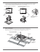
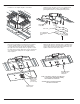
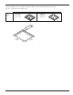
Step 6 INSTALL CARRIAGE BOLTS
Drill (4) Ø 9/32" [7.1mm] holes through deck using rectangular openings in mounting plate as a
guide. Remove carriage bolts from temporary fasteners and drop through holes. Align rectangular
shaft and seat into plate. Secure carriage bolt in place by bending tab over head of bolt.
2. Remove Carriage Bolt from Mounting
Plate and drop into square opening.
1. Drill Ø 9/32" [7.1mm] hole
through rectangular opening.
3. Pry Tab up over
Screw Head.
4. Secure Carriage Bolt
by bending Tab over
Head of Bolt.
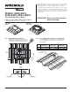
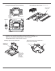
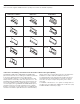
Step 5B RFB4-4DBFC – INSERT TUNNELING BARRIERS
Determine power/communication distribution inside of box and insert tunneling barrier(s) into holes in cover/device
plate mounting bracket. Flatten tip of barrier(s) with hammer to lock in place while installing bracket. Fit molded
housing over baseplate and attach bracket with #10-24x5/8" screws to baseplate
Tunneling for (2) Power & (2) Communication Tunneling for (1) Power & (3) Communication or
(3) Power & (1) Communication
POWER
POWER
DATA
DATA
POWER
POWER
POWER
DATA
Barrier
Barrier
Flatten tip of Barrier projecting
above Cover/Device Plate
Mounting Bracket