
Data Sheet


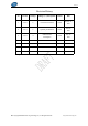


Table Of Contents

V1.0.2
Copyright ©2020 Wireless-Tag Technology Co., Ltd. All Rights Reserved. http://www.wireless-tag.com 4
Table 1 Pin Definitions and Descriptions
Pin
Name
Description
1
IO0
GPIO0, ADC1_CH0, XTAL_32K_P (32.768 kHz crystal input)
2
IO1
GPIO1, ADC1_CH1, XTAL_32K_N (32.768 kHz crystal output)
3
EN
Chip Enable pin:
High level: on, enables the chip.
Low level: off, low current.
Note:
Do not leave the EN pin floating.
4
IO2
GPIO2, ADC1_CH2, FSPIQ
5
IO4
GPIO4, MTMS, ADC1_CH4, FSPIHD
6
IO5
GPIO5, MTDI, ADC2_CH0, FSPIWP
7
IO6
GPIO6, MTCK, FSPICLK
8
VCC
3.3V power supply; The output current delivered by the external
power supply is recommended to be above 500mA.
9
IO18
GPIO18, USB_D
10
IO19
GPIO19, USB_D+
11-14
NC
NC
15
GND
GND
16
IO7
GPIO7, MTDO, FSPID
17
IO8
GPIO8
18
IO9
GPIO9
19
IO10
GPIO10, FSPICS0
20
IO3
GPIO3, ADC1_CH3
21
RXD0
U0RXD, GPIO20
22
TXD0
U0TXD, GPIO21
3.3 Strapping Pins
ESP32-C3 series has three strapping pins.
GPIO2
GPIO8
GPIO9
Software can read the strapping values of these pins in “GPIO_STRAPPING” register.
During the chip’s system reset(power-on reset, RTC watchdog reset, brownout reset, analog super