
Installation Manual


21
CONFIDENTIAL UNDER NON-DISCLOSURE AGREEMENT (NDA)
Rev A1
Document:
WSS 4G Ground Installation Manual 750-
00004-00 Reva1.Docx
July -30
2020
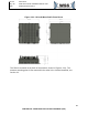
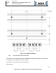
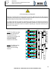
NOTE: The RRH has eight
transmitters operating at
the same time and
connected to all eight ports
of the phased array
antenna via phase
matched coax cables.
NOTE: The RRH has four
identical transceivers
(AD9371) from Analog
Devices.
XILINX
FPGA
XCKU035
PA
PA
PA
PA
0°
90°
90°
0°
RVS
Power
Detector
RVS
Power
Detector
FW
Power
Detector
FW
Power
Detector
Amp
Step
ATT
LNA
Step
ATT
Amp
BALUN
BALUN
Ant A
BALUN
ORx1
Transceiver 1
ORx2
Tx1
Rx1
Tx2
Rx2
JESD204B
CONTROL
JESD204B
CONTROL
JESD204B
CONTROL
JESD204B
CONTROL
CPRI Interface
ARM
GPMC
Clock Distributer
Clock
Clock
Transceiver
Clock
X4
122.88MHz
Ref Clock
Test and
Debug
Conn’
ETH
PHY
RS-232
RS-232
CPLD
JTAG
JTAG
JTAG
JTAG
GPIO
GPIO
GPIO
SDRAM
DDR3
GMII
MDIO
NOR
FLASH
SPI
Power
Mon
SPI
NOR
FLASH
SPI
RGMII
IO Signals
IO Signals
NAND
FLASH
GPMC
GPMC
I2C SPI
I2C SPI
SPI
SPI
SPI
SPI
Transceiver 1-4
SPI
I2C
BF
Filter Clam Shell
CPLD CLK
32.768KHz
Clocks
122.88 MHz
(FPGA, ARM,
Transceivers)
25MHz
(FPGA, CPLD,
ARM)
32.768KHz
(CPLD Clock)
1MHz
(ARINC429 Ref
Clock)
VCO
122.88MHz
Phase
Alignment
Board
Phase
Alignment
Board
PA
PA
PA
PA
0°
90°
90°
0°
RVS
Power
Detector
RVS
Power
Detector
FW
Power
Detector
FW
Power
Detector
Amp
Step
ATT
LNA
Step
ATT
Amp
BALUN
BALUN
Ant C
BALUN
ORx1
Transceiver 2
ORx2
Tx1
Rx1
Tx2
Rx2
Filter Clam Shell
Phase
Alignment
Board
Phase
Alignment
Board
PA
PA
PA
PA
0°
90°
90°
0°
RVS
Power
Detector
RVS
Power
Detector
FW
Power
Detector
FW
Power
Detector
Amp
Step
ATT
LNA
Step
ATT
Amp
BALUN
BALUN
Ant E
BALUN
ORx1
Transceiver 3
ORx2
Tx1
Rx1
Tx2
Rx2
Filter Clam Shell
Phase
Alignment
Board
Phase
Alignment
Board
PA
PA
PA
PA
0°
90°
90°
0°
RVS
Power
Detector
RVS
Power
Detector
FW
Power
Detector
FW
Power
Detector
Amp
Step
ATT
LNA
Step
ATT
Amp
BALUN
BALUN
Ant G
BALUN
ORx1
Transceiver 4
ORx2
Tx1
Rx1
Tx2
Rx2
Filter Clam Shell
Phase
Alignment
Board
Phase
Alignment
Board
PA
PA
PA
PA
0°
90°
90°
0°
RVS
Power
Detector
RVS
Power
Detector
FW
Power
Detector
FW
Power
Detector
Amp
Step
ATT
LNA
Step
ATT
Amp
BALUN
BALUN
Ant B
BALUN
Filter Clam Shell
Phase
Alignment
Board
Phase
Alignment
Board
PA
PA
PA
PA
0°
90°
90°
0°
RVS
Power
Detector
RVS
Power
Detector
FW
Power
Detector
FW
Power
Detector
Amp
Step
ATT
LNA
Step
ATT
Amp
BALUN
BALUN
Ant D
BALUN
Filter Clam Shell
Phase
Alignment
Board
Phase
Alignment
Board
PA
PA
PA
PA
0°
90°
90°
0°
RVS
Power
Detector
RVS
Power
Detector
FW
Power
Detector
FW
Power
Detector
Amp
Step
ATT
LNA
Step
ATT
Amp
BALUN
BALUN
Ant F
BALUN
Filter Clam Shell
Phase
Alignment
Board
Phase
Alignment
Board
PA
PA
PA
PA
0°
90°
90°
0°
RVS
Power
Detector
RVS
Power
Detector
FW
Power
Detector
FW
Power
Detector
Amp
Step
ATT
LNA
Step
ATT
Amp
BALUN
BALUN
Ant H
BALUN
Filter Clam Shell
Phase
Alignment
Board
Phase
Alignment
Board
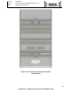
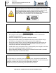
RF EXPOSURE STATEMENTS
Exposure to radio frequency during wireless operation: Based on the FCC RF exposure
compliance requirements, the separation distance between a wireless antenna and any
person’s body must be at least 21.26 inches [54 cm].
To comply with FCC RF exposure compliance requirements, the antenna used for this
transmitter must be installed to provide a separation distance of 21.26 inches [54 cm]
from all persons and must not be co-located or operating in conjunction with any other
antenna or transmitter.