
Installation Manual

52
CONFIDENTIAL UNDER NON-DISCLOSURE AGREEMENT (NDA)
Rev A1
Document:
WSS 4G Aircraft Installation Manual 750-
00003-00 Reva1.Docx
July -30
2020
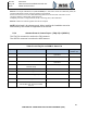
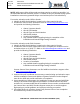
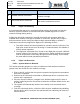
Figure 5.2.4-1 FDQ P1 and HPB P1Shield Terminations
Note 11: After stripping cable outer jacket, secure ends of braided shield and foil shield using insulation
sleeving indicated.
Note 12: Fit a length of braid wire, IN (ITEM NUMBER) 17, such that it covers the cable outer jacket, the
exposed cable shield, and the connector chimney or back-shell.
Secure one end of IN 17 on the cable shield using IN 8, and secure the other end of IN 17 to the
connector chimney or back-shell, again using IN 8.
Completely cover IN 17 using boot seal, IN 18, or sleeving, IN 27, 28 as indicated.
NOTE: Wire listed is for reference only. Wires used for the installation are to be
determined by the installer as applicable to the aircraft.
Caution: Verify proper wiring and pins for 28 VDC Power and Ground from ABR
to FDQ and HPB Antennas. Reverse polarity of the DC power connection will
damage ABR.
5.2.5
ABR CWAP & Maintenance Eth. Outputs (P2-C & P2-D)
The P2-C connection is used for the Maintenance port which is a 1000Base-T
connection.
The P2-D connection is used for the CWAP port which is a 1000Base-T connection.