
Installation Manual

51
CONFIDENTIAL UNDER NON-DISCLOSURE AGREEMENT (NDA)
Rev A1
Document:
WSS 4G Aircraft Installation Manual 750-
00003-00 Reva1.Docx
July -30
2020
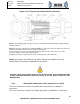
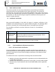
Note 12: Fit a length of braid wire, IN (ITEM NUMBER) 17, such that it covers the cable outer jacket, the
exposed cable shield, and the connector chimney or back-shell.
Secure one end of IN 17 on the cable shield using IN 8 and secure the other end of IN 17 to the
connector chimney or back-shell, again using IN 8.
Completely cover IN 17 using boot seal, IN 18, or sleeving, IN 27, 28 as indicated.
Note 20: Cables are cinched together when IN 8 is crimped.
NOTE: Wire listed is for reference only. Wires used for the installation are to be
determined by the installer as applicable to the aircraft.
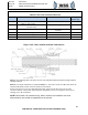
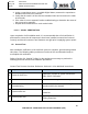
5.2.4
Antenna Power & Control input – (FDQ P1) & (HPB P1)
The FDQ P1 connector is used on the FDQ antenna.
The HPB P1 connector is used on the HPB antenna.
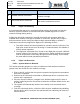
Table 5.2.4-1 FDQ P1 and HPB P1 Parts List
Quantity
Manufacturer & Description
Part Number
Drawing Item
Number (IN)
A/R
Cable, 22AWG/4 COND
M27500-22TG4T14 or
equivalent
15
A/R
Cable, 24AWG/4 COND
E10424 or equivalent
12
1
Braid Wire (36AWG, .500DIA)
AA59569R36T0500 or
equivalent
17
4
GlenAir
Tie-down Strap
600-057 or equivalent
8
A/R
Insulation Sleeving (.063- .031)
M23053/5-102-0
36
A/R
Insulation Sleeving (.750- .313)
M23053/4-106-0
29
A/R
Insulation Sleeving (.375)
M23053/4-104-0
27
A/R
Insulation Sleeving (.500-.195DIA)
M23053/4-105-0
28
2
Amphenol
Circular MIL Spec Connector 26482
Size 12
MS3126E12-10S
30