
Installation Manual

40
CONFIDENTIAL UNDER NON-DISCLOSURE AGREEMENT (NDA)
Rev A1
Document:
WSS 4G Aircraft Installation Manual 750-
00003-00 Reva1.Docx
July -30
2020
5.0
SYSTEM INTERCONNECTS
5.1
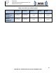
Connector List and Descriptions
This section details the system interconnect requirements for proper cabling and
interconnection of the WSS System.
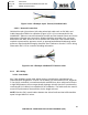
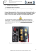
The J1 and J2 connectors for the ABR are keyed for proper alignment with the ABR
receptacle. When assembling the connectors, ensure that the keyways are installed so
that the keyway opening is in the 12 o’clock position between the numbers ‘1’ and ‘6’
etched on the connector housing. See figure 5.1.1-1 below for proper alignment.
The assembly of the plug keying component on the cabling harness does not
require the use of any tools. If the plug keying component p/n 732-8020-10 is
incorrectly installed in the connector cavity, it must be broken to be removed. Use
caution when assembling the ABR connectors. See figures below for keying
alignment reference.
Figure 5.1.1-1 ABR Connector Keying Alignment Reference