
Installation Manual

38
CONFIDENTIAL UNDER NON-DISCLOSURE AGREEMENT (NDA)
Rev A1
Document:
WSS 4G Aircraft Installation Manual 750-
00003-00 Reva1.Docx
July -30
2020
aircraft per industry best practice. Secure the cable to the aircraft structure at FAA-
compliant intervals. Use approved lacing tape, or equivalent, to secure any length of
cable otherwise unsupported, such as the 1000BASE-T Maintenance Port using
industry best practice.
NOTE: Prior to connecting to the aircraft antennas, refer to Section 6.1 Installation
Verification.
4.3
ABR Chassis Installation
After the cable harness installation has been completed, mount the chassis tray to the
aircraft avionics rack in a manner consistent with the mounting requirements described
in Section 3.5.2 of this manual.
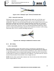
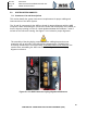
Guide the ABR into the tray with the connector panel facing out, lining up the guide pins
in the back, and securing the front swing-bolts to the mounting feet on the ABR box.
Install swing bolt lower part onto the mounting hooks, and hand tighten by turning the
knob clockwise until fully seated. No tool is required for installation and a measurement
of torque is not required.
Connect the cables to the ABR per Section 5.0 System Interconnects guidance.
Bonding- The electrical bond between the installed ABR, mounting tray and airframe
ground should not exceed 2.5 milliohms. Refer to Advisory Circular 43.13-1b chapter 15
for additional guidance.
Caution: Verify proper wiring and pins for 28 VDC Power and Ground from ABR to FDQ
and HPB Antennas. Reverse polarity of the DC power connection may damage the ABR.