
Installation Manual

37
CONFIDENTIAL UNDER NON-DISCLOSURE AGREEMENT (NDA)
Rev A1
Document:
WSS 4G Aircraft Installation Manual 750-
00003-00 Reva1.Docx
July -30
2020
4.0
INSTALLATION PROCEDURE
This section provides the necessary information for successful installation of the WSS
4G System. Guidance for the installation of the WSS ABR is provided by RTCA
Standard DO-313, “Certification Guidance for Installation of Non-Essential, Non-
Required Aircraft Cabin Systems and Equipment,” and FAA Advisory Circulars AC
43.13-1B, AC43.13-2B, and AC20-168.
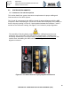
4.1
Antenna Installation
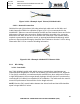
An example antenna drawing for the HPB antenna is shown in Figure 2.3.2-1/2 and for
the FDQ antenna is shown in Figure 2.3.2-3. Refer to the manufacturer’s drawings for
the antenna mounting screw torque values required to install the antennas to the
aircraft. The STC applicant will need to determine if the recommended torque values
need to be modified based on material mounting, such as honeycomb, skin/shim, etc.
The following guidance is provided for installation. See AC 43.13-1B for additional
guidance on antenna installation.
1.
Bonding- Antennas mounted on composite aircraft panels must provide an
electrical bond of 10.0 milliohms or less to the airframe ground. Bonding of the
antenna may be accomplished through the mounting hardware, attached to an
internal doubler plate with a suitable ground strap between the doubler plate and
the airframe provide that the resistance between the antenna and airframe meets
the requirements of this section. Antennas mounted on sheet metal aircraft
panels must provide an electrical bond of 2.5 milliohms or less to the airframe
ground. Refer to Advisory Circular 43.13-1b chapter 15 for additional guidance.
2.
Apply an electrical bonding agent between the antenna and the fuselage skin
using Av-DEC or equivalent gaskets or appropriate conductive paste.
3.
All interface surfaces of antenna doublers and edges of the antenna fillet areas
and feed-through holes for the antennas are to be sealed with PRC DeSoto Pro-
Seal 870 or equivalent.
4.
Seal the antenna attaching screw holes with RTV 162 sealant or equivalent and
contour to match the antenna.
5.
DO NOT PAINT ANTENNA RADOME. Painting the antenna’s radome will
degrade the performance of the system and may void warranty. If touch-up is
required, use Polyurethane MIL-PRF-85285, Color number 27875.
6.
The edge of the FDQ antenna’s aluminum baseplate can be painted if desired.
NOTE: For both FDQ and HPB antenna installation, it is acceptable to use 10-32
countersunk 100-degree flat screw head as an alternative to 10-32 countersunk 100-
degree oval screw head. Recommended torque for both is 25 in-lbs.
4.2
ABR Cable Installation
Run the coaxial and control cable harnesses through the aircraft as planned by the
installer. Ensure that bend radii are greater than the values specified by the
manufacturer, the cables are protected from sharp airframe structural components, and
are routed appropriately to address the unique routing locations/environment of the