
Installation Manual

33
CONFIDENTIAL UNDER NON-DISCLOSURE AGREEMENT (NDA)
Rev A1
Document:
WSS 4G Aircraft Installation Manual 750-
00003-00 Reva1.Docx
July -30
2020
Extreme care should be taken with cable assembly, as minor defects in cable
termination can greatly increase VSWR and/or attenuation of cable assemblies and
compromise system performance. Cable assemblies should be tested after assembly,
and again after installation in the airframe to ensure no installation handling damage
has occurred. It is recommended that the VSWR of the installed cabling system be less
than 1.5:1, and attenuation be no greater than the maximum specified below. The
‘cabling system’ is defined as the connector-terminated cables, and any in-line bulkhead
connector(s) required.
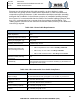
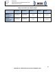
Table 3.6.4-1 Coax Cable Requirements
Characteristics
Specification
Cable Impedance
50 Ω
Operating Temperature Range
-55°C to 125°C
Velocity of Propagation (ʋ
p
)
85% [± 5%]
Shielding of Effectiveness
> 90dB through 18 GHz
Maximum Attenuation / dB
Loss (including connectors)
•
ABR to FDQ/HPB Rx coax cables:< 6.0 dB @ 2.483 GHz
•
ABR to FDQ Tx coax cable: < 3.0 dB @ 2.483 GHz.
•
ABR to HPB embedded GPS: < 10.0 dB @ 1.5 to 1.6 GHz.
Maximum VSWR (including
connectors)
1.5:1
Flammability
Federal Aviation Regulations 14 CFR Part 25.869(a) (4) Amendment 25-
113, Appendix F Part I(a)(3)
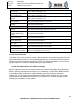
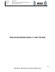
Table 3.6.4-2 Recommended Coax Cable Compliance
Condition
Compliance Standard
Vapor Leakage
MIL-STD-202 Method 112E, paragraph 5, test condition C, procedure IV
Temperature Shock
MIL-STD-810, Method 503.2
Vibration
MIL-STD-810, Method 514.3, Procedure I
Power Handling Capability
MIL-T-81490, paragraph 4.7.13
Flexure
MIL-T-81490, paragraph 4.7.15