
Installation Manual

31
CONFIDENTIAL UNDER NON-DISCLOSURE AGREEMENT (NDA)
Rev A1
Document:
WSS 4G Aircraft Installation Manual 750-
00003-00 Reva1.Docx
July -30
2020
• Check that there is ample space for the cabling and mating connectors. Avoid sharp
bends in cabling. Refer to the manufacturer’s minimum bend radius
recommendations.
• When routing antenna cables, observe the following precautions:
− All cable routing should be kept as short and direct as possible.
− Avoid routing cables near power sources (e.g., 400 Hz generators, trim motors,
etc.) or power or ballasts for fluorescent lighting.
− Avoid routing cable near ADF antenna cable.
− Avoid routing cables near the aircraft’s GPS system antenna or power cables.
− Avoid routing cables near the aircraft’s transponder and DME system
3.6.2
DC Power (Radio and Antennas)
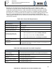
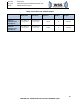
Installers should select the appropriate capacity circuit breaker to provide full rated
current to the system as defined in Table 2-1. Reference Section 5.1.3 for DC Power
wiring definitions. For additional guidance, refer to applicable FAA regulatory
requirements and guidance for circuit protective devices.
Caution: Verify proper wiring and pins for 28 VDC Power and Ground from ABR to FDQ
and HPB Antennas. Reverse polarity of the DC power connection will damage ABR.
3.6.3
Control and Network Cabling
All network and control cabling should to be shielded, controlled-impedance twisted
pairs to ensure signal integrity and reject noise. Pair twist should be maintained to
within a maximum recommended distance of 0.5” to the connector module entry points
to minimize crosstalk between pairs.
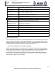
Note that two pairs are crisscross arranged through the connector body. This minimizes
crosstalk between the pairs while passing through the connector. Special attention
must be paid to the wire pairing at both ends of the cable for digital signals. Failure to
maintain wire pairing will result in high crosstalk in the cabling. Pin numbering in the
diagrams conforms to industry standard TIA-568B pairs: 1-2, 3-6, 4-5, 7-8
3.6.3.1
Antenna Control Connections
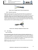
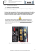
Shielded two-pair (4-conductor) 100-ohm twisted pair cable such as PIC Wire and
Cable Datamates E10424 or equivalent (Figure 3.6.3.1-1) is recommended for the
control connection between the ABR and each antenna. Reference Section 5.1.3 for
wiring information and 5.2.3 for connector shielding requirements.