
Specifications


Ô
34
Wireless Connectivity Guide Texas Instruments 4Q 2014
Sub-1 GHz
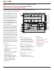
CC1110
Radio, MCU and Flash
all-in-one chip
The CC1110Fx family consists of
three Systems-on-Chip designed for
low-power and low-voltage wireless
communication applications. With
a 315/433/868/915-MHz radio
transceiver, a single-cycle 8051 MCU,
8/16/32-kB Flash memory and
additional peripherals, these unique
all-in-one devices make it easier than
ever to finish your design faster while
offering numerous application
possibilities.
Key features
• High-performance,low-power8051
MCU core, typically with 8× the per-
formance of a standard 8051
• Utilizesthehigh-performance
CC1101 RF transceiver core
• 8/16/32-kBin-system
programmable Flash
• 1/2/4-kBSRAM(withdataretention
in all power modes)
• 8-to12-bitADC,21generalpurpose
I/O pins, on-chip timers
• Veryfewexternalcomponents
required
• Fourflexiblepowermodesfor
reduced power consumption
• Veryfasttransitiontimesfromsleep
modes to active mode enables
ultra-low average power consumption
in low duty-cycle systems
• Indeep-sleepmodesthesystemcan
wake up on external interrupts or
real-time counter events
• Lowcurrentconsumption
• AES-128encryptioncoprocessor
• PowerfulDMAfunctionality
• Real-timeclockwithlow-power
32.768-kHz crystal oscillator or inter-
nal 34-kHz RC Oscillator
Benefits
• Completesolutionononesinglechip
• Idealforlow-power,battery
operated systems
• Robustandsecurelinkwithvery
good coexistence
RF System-on-Chip Solution
CC1110F8/F16/F32
Get samples, datasheets, evaluation modules and application notes at:
www.ti.com/product/cc1110f32
See also: www.ti.com/product/tps62730
Applications
• Alarmandsecurity
• Automaticmeterreader/
smart metering
• Consumerelectronics
• Wirelessnetworkstargeting
IEEE 802.15.4g standard
Development tools and software
• CC1110/CC1111DK
Development Kit
• CC1110EMK-433MHz
Evaluation
Module Kit
• CC1110EMK-868/915MHz
Evaluation Module Kit
• SimpliciTI™softwareprotocol
• WirelessM-Bus
• CC1110DK-MINI
P1_2
DVDD
P1_1
P1_0
P1_0
P0_1
P0_2
P0_3
P0_4
P1_3
P1_4
P1_5
P1_6
P1_7
RESET_N
DCOUPL
AVDD_DREG
GUARD
R_BIAS
AVDD
AVDD
RF_N
RF_P
AVDD
XOSC_Q1
XOSC_Q2
AVDD
AGND
Exposed Die
Attached Pad
C301
2.0 V to 3.6 V
Power Supply
Antenna
(50 Ω)
R271
C241
C231
C234
C211
X2
C171
Optional:
C181
X1
L232
L233
C235
C232
C233
L231
CC1110
DVDD
PO_5
PO_6
PO_7
P2_0
P2_1
P2_2
P2_4/XOSC32_Q1
P2_4/XOSC32_Q2
L241
1
2
3
4
5
6
7
8
9
C201
27
26
25
24
23
22
21
20
19
10 11 12 13 14 15 16 17 18
36 35 34 33 32 31 30 29 28
General Characteristics
Parameter
(433/868 MHz, 3.0 V, 25°C) Min Typ Max Unit Condition
Operating conditions
Frequencyrange 300 — 348 MHz
391 — 464 MHz
782 — 928 MHz
Operatingtemperaturerange –40 — +85 ºC
Operatingsupplyvoltage 2.0 — 3.6 V
Datarate(programmable) 1.2 — 500 kBaud
Outputpower(programmable) –30 — 10 dBm
Receiversensitivity — –111 — dBm 1.2kBaud,868MHz,1%packeterrorrate
Current consumption
MCUactiveandRXmode — 17 — mA Systemclockat203kHz
MCUactiveandTXmode,0dBm — 20/21 — mA
MCUrunningatfullspeed(26MHz),radioinTX
mode,0-dBmoutputpower
Powermode2 — 0.5 — µA
32kHzRC-oscillator(or32.768-kHzcrystal
oscillator)andsleeptimerrunning
Powermode3 — 0.3 — µA
Noclocksrunning,powerOnReset(POR)active,can
wakeuponexternalinterrupt
Wake-up and timing
Frompowermode2or3toactive — 100 — µs
Digitalregulatorandhigh-speedoscillatorsoff,
start-upofregulatorandhigh-speedRCOscillator
FromactivetoRXorTX — 90 — µs
Timefromenabling26-MHzcrystaloscillatorandthe
radiopartuntilRXorTXstarts
For quicker integration use a
Chip Balun from our third party
developer.