
User manual

6 BlackBox and WhiteBox F-2
2012-02 W-DMX G4 User Manual, edition 1 27
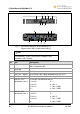
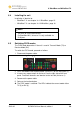
No. Port Description
8 DC power input Input for Phoenix Gold Connector:
• Left: Ground
• Right: +12 V DC
9 DMX OUT / bypass XLR female 5 pin output (BlackBox MK II only) for Univ 2
10 DMX IN XLR male 5 pin input (BlackBox MK II only) for Univ 2
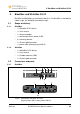
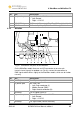
6.2.2 WhiteBox
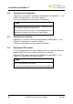
Fig. 8: Connectors and ports of the WhiteBox
On the WhiteBox models there are no XLR connectors to ensure safe
transmission of signals for outdoor use. For this reason the connection to
DMX signal cables differs slightly to the BlackBox models, which are for indoor
use only.
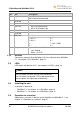
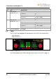
No. Port Description
1 Cord Strip For AC power input (2)
2 AC power input 90 – 250 V AC
• Left: Outer conductor (L)
• Middle: Ground (GND)
• Right: Neutral conductor (N)
3 Cord Strip For DC power input (4)
4 DC power input Phoenix Gold Connector 12 V DC
• Left: Ground
• Right: +12 V DC
5 Cord Strip For signal cable (DMX or Ethernet)