
User manual

4 BlackBox and WhiteBox F-1
2012-02 W-DMX G4 User Manual, edition 1 15
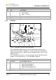
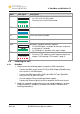
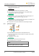
Name LED signal Description
G4
G4 (off)
G4 (on)
G4 (flashing)
• Off: Unit in G3 mode
• On: Unit in G4 2.4 GHz mode
• Flashing: Unit in G4 5.8 GHz mode
PWR
POWER (off)
POWER (on)
Power on / off
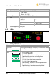
RX
RX (on)
Unit in RX (receiver) mode
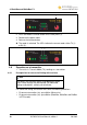
DATA
DATA (on)
Data is available at the input / output
RDM
RDM (off)
WhiteBox: included, BlackBox: optional
• Off: No RDM data is available at the input / output for
a minimum of 2 seconds.
• On: RDM data is available at the input / output
CTRL
CTRL (off)
CTRL (flashing)
• Off: Normal operation
• Flashing: CTRL mode to set the frequency band, see
chapter "4.8 Switching CTRL modes", page 21
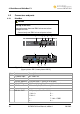
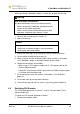
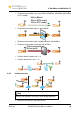
4.4 Installing the unit
4.4.1 BlackBox
1. Choose one of the following options to make the DMX connection:
– Connect the DMX source to the XLR 5 pin DMX IN port (BlackBox only)
or the to the RJ 45 DMX IN port.
– Connect the DMX fixture to the XLR 5 pin DMX OUT port (BlackBox
only) or the RJ 45 DMX OUT port.
– Unit with optional Ethernet lighting protocol support:
Connect the Ethernet lighting source or output to the Ethernet in port.
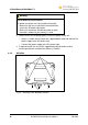
2. Attach the supplied standard antenna(s) and standard adapter(s) or other
suitable antenna(s) / adapter(s) available from Wireless Solution to the
matching connector(s).