
User manual

4 BlackBox and WhiteBox F-1
14 W-DMX G4 User Manual, edition 1 2012-02
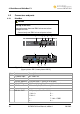
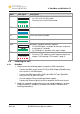
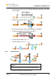
No. Port Description
4 DC power input Phoenix Gold Connector 12 V DC
• Left: Ground
• Right: +12 V DC
5 Cord Strip For signal cable (DMX or Ethernet)
RJ45 port:
1: Univ 1+ 5: –
2: Univ 1– 6: –
3: – 7: Univ 1 GND
6 DMX
4: – 8: –
7 Ethernet (optional) RJ45 port
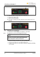
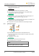
4.3 LEDs
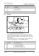
Fig. 4: LEDs of F-1
Name LED signal Description
Signal bar – Currently received signal strength (in RX (receiver) mode)
TX
TX (on)
Unit in TX (transmitter) mode
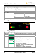
LINK
LINK (off)
LINK (on)
LINK (flashing)
LINK (rapid flashing)
In TX (transmitter) mode:
• On: Normal operation
• Slow flashing: Receivers are being unlinked
• Rapid flashing: Receivers are being linked
In RX (receiver) mode:
• Off: Unit is not linked to any transmitter
• On: Unit is linked to transmitter
• Slow flashing: Transmitters are being searched or
linked transmitter is lost.
• Rapid flashing: Transmitters are being linked