
User manual

4 BlackBox and WhiteBox F-1
4.2 Connectors and ports
4.2.1 BlackBox
Caution
Damage to the unit!
Connecting more than one DMX universe at a time
damages the unit.
• Connect only one DMX universe input at a time.
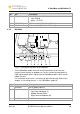
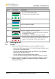
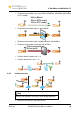
1
23
4
5
8
7
6
Fig. 2: Connectors and ports of F-1
(Upper picture: MK I; lower picture: MK II)
No. Port Description
1 AC power input 90 – 250 V AC
2 Reserved –
3 Ethernet (optional) RJ45 port (MK II : EtherCon RJ45 port)
4 DMX OUT bypass XLR female 5 pin (BlackBox only) universe 1
5 DMX IN XLR male 5 pin (BlackBox only) universe 1
6 Reserved –
RJ45 port (not BlackBox MK II):
1: Univ 1+ 5: –
2: Univ 1- 6: –
3: – 7: Univ 1 GND
7 DMX IN / OUT:
4: – 8: –
12 W-DMX G4 User Manual, edition 1 2012-02