W-DMX G4 BlackBox and WhiteBox F-1 BlackBox and WhiteBox R-512 BlackBox and WhiteBox F-2 Micro F-1 Lite Micro R-512 Lite ProBox F-2500 User Manual
W-DMX G4 User Manual Issue date: 2012-02 Edition: 1 Subject to modifications. All trademarks referenced are trademarks or registered trademarks of their respective owners, whose protected rights are acknowledged. Copyright Wireless Solution Sweden Sales AB Wireless Solution Sweden Sales AB Stureparksvägen 7 451 55 Uddevalla Sweden Tel.: +46 522 511 511 Fax: +46 522 440 885 E-Mail: helpdesk@wirelessdmx.com Web: www.wirelessdmx.
Contents Contents 1 Your Wireless DMX G4 system (W-DMX G4) ..................................................... 7 2 The W-DMX technology....................................................................................... 8 3 About this document ......................................................................................... 10 4 3.1 Target group of this document ................................................................ 10 3.2 Signs and symbols in this document ................
Contents 6 5.3 LEDs ....................................................................................................... 24 5.4 Installing the unit ..................................................................................... 24 5.5 Operation as a receiver ........................................................................... 24 BlackBox and WhiteBox F-2 ............................................................................. 25 6.1 6.2 7 6.1.1 BlackBox .....................
Contents 8 9 ProBox F-2500.................................................................................................... 36 8.1 Scope of delivery..................................................................................... 36 8.2 Connectors and ports.............................................................................. 36 8.3 LEDs ....................................................................................................... 37 8.4 Installing the unit .................
1 Your Wireless DMX G4 system (W-DMX G4) 1 Your Wireless DMX G4 system (W-DMX G4) Thank you for purchasing the Wireless DMX G4 system (W-DMX G4), the industry’s leading system for transmitting and receiving DMX signals reliably.
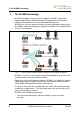
2 The W-DMX technology 2 The W-DMX technology W-DMX technology is the core of all our products. W-DMX is specifically engineered by Wireless Solution Sweden AB to provide the same quality, reliability and performance as in any hardwired DMX data link. W-DMX gives you even greater freedom to create reliable point-to-point, pointto-multipoint and even multipoint-to-multipoint installations over large distances and in any environment. Fig.
2 The W-DMX technology • The complex communication protocols are fully automated and concealed from view - you just plug-and-play, the W-DMX G4 units do all the hard work. • From the DMX connector of one W-DMX G4 unit to the DMX connector of another, the W-DMX system is totally transparent. The W-DMX G4 system includes additional features that help to enhance reliability: both in its installation in any type of environment as well as in its stable operation.
3 About this document 3 3.1 About this document Target group of this document This document is designed for lighting designers, lighting operations managers and lightning technicians. W-DMX is an easy-to-use plug-and-play system. Basic knowledge of lighting technologies is an advantage. Every user has to be familiar with local regulations regarding frequencies and their usage. For advanced settings and projects, please contact your distributor. 3.
4 BlackBox and WhiteBox F-1 4 BlackBox and WhiteBox F-1 BlackBox and WhiteBox are functionally identical. The BlackBox is intended for indoor usage, the WhiteBox for outdoor usage. 4.1 4.1.1 4.1.
4 BlackBox and WhiteBox F-1 4.2 4.2.1 Connectors and ports BlackBox Caution Damage to the unit! Connecting more than one DMX universe at a time damages the unit. • Connect only one DMX universe input at a time. 1 8 2 3 7 6 4 5 Fig. 2: Connectors and ports of F-1 (Upper picture: MK I; lower picture: MK II) No.
4 BlackBox and WhiteBox F-1 No. Port Description 8 DC power input Input for Phoenix Gold Connector: • Left: Ground • Right: +12 V DC 9 DMX OUT bypass XLR female 3 pin (BlackBox MK II only) 10 DMX IN 4.2.2 XLR male 3 pin (BlackBox MK II only) WhiteBox Fig. 3: Connectors and ports of the WhiteBox On the WhiteBox models there are no XLR connectors to ensure safe transmission of signals for outdoor use.
4 BlackBox and WhiteBox F-1 No. Port Description 4 DC power input Phoenix Gold Connector 12 V DC • Left: Ground • Right: +12 V DC 5 Cord Strip For signal cable (DMX or Ethernet) 6 DMX RJ45 port: 7 4.3 1: Univ 1+ 5: – 2: Univ 1– 6: – 3: – 7: Univ 1 GND 4: – 8: – Ethernet (optional) RJ45 port LEDs Fig.
4 BlackBox and WhiteBox F-1 Name G4 LED signal G4 (off) G4 (on) Description • • • Off: Unit in G3 mode On: Unit in G4 2.4 GHz mode Flashing: Unit in G4 5.8 GHz mode G4 (flashing) PWR POWER (off) Power on / off POWER (on) RX RX (on) Unit in RX (receiver) mode DATA DATA (on) Data is available at the input / output RDM RDM (off) WhiteBox: included, BlackBox: optional • Off: No RDM data is available at the input / output for a minimum of 2 seconds.
4 BlackBox and WhiteBox F-1 Warning Risk of death by electrocution! AC power connection must be carried out correctly. • • Make sure that only a qualified, trained electrician carries out AC power connection. Make sure the correct Schuko connector or other connector suitable for your country is used. 3. Choose one of the following options to connect power to the unit: – Attach a suitable mains plug to the supplied power cord and connect the power supply to the AC power input.
4 BlackBox and WhiteBox F-1 When connecting a WhiteBox model it is necessary to open the housing. Warning Risk of death by electrocution! AC power connection must be carried out correctly. • • Make sure that only a qualified, trained electrician carries out AC power connection. Make sure the correct Schuko connector or other connector suitable for your country is used. 1. Unscrew the housing by the 4 screws (1). 2. Open the housing.
4 BlackBox and WhiteBox F-1 1 2. Press and hold the function button on the front panel (1). 3. Reconnect the power cable. 4. Release the function button. The mode is switched. The LEDs indicate the current mode: either TX (1) or RX (2): 1 2 4.6 Operation as a transmitter The unit is in Transmit Mode (TX), working as a transmitter. 4.6.1 Prerequisites for successful linking with receivers Hint The figures are maximum figures and depend on output levels. Local settings may be required.
4 BlackBox and WhiteBox F-1 Distance to transmitter (air): up to 750 m (BlackBox, WhiteBox and ProBox in FCC mode) 200 m (Micro) 500 m (ETSI mode) 700 m (FCC mode) Tx Rx Distance to transmitter (glass): up to 500 m Distance to transmitter (wall, except concrete): up to 350 m Distance to transmitter (concrete): up to 150 m 150 m (concrete) 350 m (wall) Tx Rx Position above crowds: min. 1 m Position above trees: min. 1 m Tx Rx Min 1m Tx 4.6.2 Rx Linking receivers 1. 2. 3.
4 BlackBox and WhiteBox F-1 2. Ensure that the receiver is not connected to any other transmitter, i.e., the LINK LED on the receiver is off. LINK (off) 3. Press the function button of the transmitter for 1 second. The transmitter scans for all unlinked receivers for a period of about 10 seconds. The LINK LED flashes rapidly. LINK (rapid flashing) If the connection is successful, the LINK LED on the receiver goes on. If DMX input is available, the DATA LED goes on as well.
4 BlackBox and WhiteBox F-1 4.7 Operation as a receiver The unit is in Receive Mode (RX), working as a receiver. 4.7.1 Linking with transmitters Hint During the link procedure the DMX transmission is interrupted. 1. Power on the receiver. 2. Ensure that the receiver is not connected to any other transmitter, i.e., the LINK LED on the receiver is off. LINK (off) 3. Press the function button of the transmitter for 1 second.
4 BlackBox and WhiteBox F-1 All G4 receivers automatically detect the mode the transmitter is in and adapt to it. To change the CTRL mode, proceed as follows: The unit is in Transmit Mode (TX), working as a transmitter. 1 2 1. Press and hold the function button on the front panel (1) for at least 10 seconds. Hint Keep holding the button even if the LINK LED starts blinking. This allows you to go through the unlink mode without unlinking. The CTRL LED (2) flashes. The unit is in CTRL mode. 2.
5 BlackBox and WhiteBox R-512 5 BlackBox and WhiteBox R-512 BlackBox and WhiteBox are functionally identical. The BlackBox is intended for indoor usage, the WhiteBox for outdoor usage. 5.1 5.1.1 5.1.2 5.2 5.2.
5 BlackBox and WhiteBox R-512 No. Port Description 1 AC power input 90 – 250 V AC MK II: PowerCon connector 2 Reserved – 3 Reserved – 4 DMX OUT • • 5 DMX OUT XLR female 5 pin 6 Reserved – 7 DMX OUT RJ 45 port: 8 5.2.
6 BlackBox and WhiteBox F-2 6 BlackBox and WhiteBox F-2 BlackBox and WhiteBox are functionally identical. The BlackBox is intended for indoor usage, the WhiteBox for outdoor usage. 6.1 6.1.1 6.1.2 6.2 6.2.
6 BlackBox and WhiteBox F-2 1 8 2 3 7 6 4 5 Fig. 7: Connectors and ports of the BlackBox F-2 (Upper picture: MK I; lower picture: MK II) Hint On BlackBox F-2 MK I, the universe 2 output is only available via RJ 45 ports. No.
6 BlackBox and WhiteBox F-2 No. Port Description 8 DC power input Input for Phoenix Gold Connector: • Left: Ground • Right: +12 V DC 9 DMX OUT / bypass XLR female 5 pin output (BlackBox MK II only) for Univ 2 10 DMX IN XLR male 5 pin input (BlackBox MK II only) for Univ 2 6.2.2 WhiteBox Fig. 8: Connectors and ports of the WhiteBox On the WhiteBox models there are no XLR connectors to ensure safe transmission of signals for outdoor use.
6 BlackBox and WhiteBox F-2 No. Port Description 6 DMX IN/OUT standard for Univ 1 RJ45 port: 7 8 6.3 DMX IN/OUT standard for Univ 2 1: Univ 1+ 5: – 2: Univ 1– 6: Univ 2– 3: Univ 2+ 7: Univ 1 GND 4: – 8: Univ 2 GND RJ45 port: Ethernet (optional) 1: Univ 2+ 5: – 2: Univ 2– 6: Univ 1– 3: Univ 1+ 7: Univ 2 GND 4: – 8: Univ 1 GND RJ45 port LEDs The F-2 units are equipped with two identical sets of LEDs and function keys: • Left: Universe 1 • Right: Universe 2 Fig.
6 BlackBox and WhiteBox F-2 6.4 Installing the unit Installation is identical to: • BlackBox F-2: see chapter “4.4.1 BlackBox“, page 15. • WhiteBox F-2: see chapter “4.4.2 WhiteBox“, page 16. Notes • • 6.5 You have to install two antennas. On BlackBox MK I, Universe 2 is only available via RJ45 port. Switching FLEX modes The FLEX mode determines if the unit is used in Transmit Mode (TX) or Receive Mode (RX). To switch the FLEX mode, proceed as follows: 1. Disconnect the power cable. 1 2 3 2.
6 BlackBox and WhiteBox F-2 6.6 Operation as a transmitter Operation as a transmitter is identical to the BlackBox and WhiteBox F-1, see chapter "4.6 Operation as a transmitter", page 18. Carry out the procedures for each universe individually. Hint When you link the receivers for Universe 1, power-on only the respective receivers for Universe 1. Once the receivers for Universe 1 are connected, you can power-on the receivers for Universe 2 and link them. 6.
7 Micro units 7 Micro units 7.1 Micro F-1 Lite 7.1.1 Scope of delivery 7.1.2 • 1 x Micro F-1 Lite • 1 x User manual • 1 x External power supply unit • Adapters for several electrical outlets • 1 x Hook-and-loop belt Connectors and ports 1 2 Fig. 10: Micro F-1 Lite, side view No. Port Description 1 DMX IN XLR male 5 pin. If you want to use the unit as a receiver, you can buy an optional XLR 5-pin female-to-female adapter.
7 Micro units 7.1.3 LEDs Fig. 11: LEDs of Micro F-1 Lite SIGNAL/BATT: Identifies if the signal strength or battery power is displayed on the LED bar. Other LED signals are identical to F-1 (see chapter “4.3 LEDs“, page 14). Note Micro F-1 Lite does not have the G4 5.8 GHz mode. 7.1.4 Installing the unit 1. Choose one of the following options to make the DMX connection: – Connect the DMX source to the DMX IN / OUT port. – Connect the DMX fixture to the DMX IN / OUT port. 2.
7 Micro units 7.1.8 Switching CTRL modes The CTRL mode determines which frequency band is used and if Legacy G2/G3 units can be used in the wireless environment. Switching CTRL mode is identical to the BlackBox and WhiteBox F-1, see chapter "4.8 Switching CTRL modes", page 21. Hint This unit does not support the G4 5.8 GHz mode. 7.1.9 Battery option The W-DMX G4 Micro units are equipped with a holder for 6 AAA batteries.
7 Micro units 7.2 Micro R-512 Lite The unit is provided with a battery option, see chapter "7.1.9 Battery option", page 33. 7.2.1 7.2.2 Scope of delivery • 1 x Micro R-512 Lite device • 1 x User manual • 1 x External power supply unit • Adapters for several electrical outlets • 1 x Hook-and-loop belt Connectors and ports 1 2 Fig. 12: Micro R-512 Lite, side view No.
7 Micro units 7.2.3 LEDs Fig. 13: LEDs of Micro R-512 Lite SIGNAL/BATT: Identifies if the signal strength or battery power is displayed on the LED bar. Other LED signals are identical to F-1, see chapter “4.3 LEDs“, page 14. Note • • • 7.2.4 Micro R-512 Lite does not have the G4 5.8 GHz mode. Micro R-512 Lite does not have a transmission function, LED “TX” is never used. Micro R-512 Lite does not have RDM support. Installing the unit Installation is identical to the Micro F-1 Lite, see chapter "7.1.
8 ProBox F-2500 8 ProBox F-2500 8.1 Scope of delivery 8.2 • 1 x ProBox F-2500 device • 1 x User manual • 2 x Antennae adapter • 2 x dual band antennae indoor (2 dBi) • 1 x Phoenix gold connector • 1 x power cable without plug Connectors and ports Fig. 14: Connectors and ports of ProBox F-2500 (Upper picture: front panel; lower picture: connector rear) No. Port Description 1 Antennae Ports Connector for antennas Universe 1: left, Universe 2: right 2 Display & Buttons See chapter 6.
8 ProBox F-2500 No. Port Description 8 AC power input PowerCon 20A connector 9 Ethernet EtherCon RJ45 port Supports Power over Ethernet 802.3af 8.3 LEDs The ProBox F-2500 is equipped with two identical sets of LEDs and function keys: • Left: Universe 1 • Right: Universe 2 Fig. 15: LEDs of ProBox F-2500 For the description of the LED meanings, please refer to “4.3 LEDs“, page 14., 8.4 Installing the unit Installation is identical to the BlackBox F-1, see chapter “4.4.1 BlackBox“, page 15. 8.
8 ProBox F-2500 Hint When you link the receivers for Universe 1, power-on only the respective receivers for Universe 1. Once the receivers for Universe 1 are connected, you can power-on the receivers for Universe 2 and link them. 8.7 Operation as a receiver Operation as a receiver is identical to the BlackBox and WhiteBox F-1, see chapter "4.7 Operation as a receiver", page 21. 8.
9 Technical data 9 9.
9 Technical data BB F-1 WB F-1 BB R-512 WB R-512 BB F-2 WB F-2 Environmental conditions Ambient temperature range (standard) 0°C to 45°C Ambient Temperature range (12 VDC) 0°C to 40°C 0°C to 55°C Humidity 90% Input protocols DMX512 Yes RDM (1) Yes Optional Yes Ethernet Optional No Optional Streaming ACN Optional No Optional Art-Net / Art-Net 2 Optional No Optional BB F-1 WB F-1 BB R-512 WB R-512 BB F-2 WB F-2 Radio performance Loss of date behavior As wire Output protoc
9 Technical data 9.
9 Technical data MicroBox F-1 Lite MicroBox R-512 Lite DMX capabilities Adaptive Frequency Hopping Yes W-DMX G3 compatibility Yes License free Yes W-DMX Datasafe Redundancy Yes Radio performance External antenna No Standard range Up to 200 m (standard antenna) Expandable range Unlimited (optional antennas) Latency < 5 ms Sensitivity (0.1% PER) –97 dBm Modulation method GPSK Max. power 2.4 GHz EIRP (2) Max.
9 Technical data 9.3 ProBox F-2500 ProBox F-2500 Electrical data Regulations complied with High voltage input Low voltage input Average current (TX mode) Average current (RX mode) DC power supply Certified Worldwide (FCC, ETL, ETSI, CE, Japan, China , Russia) 90 to 250 VAC 12 VDC 450 to 700 mA / 12 VDC 200 mA / 12 VDC Phoenix Gold Connector Dimensions Format 19” rack format.
9 Technical data ProBox F-2500 Radio performance External antenna Standard range Expandable range Latency Sensitivity (0.1% PER) Modulation method Yes Up to 750 m Unlimited < 5 ms –97 dBm GPSK Max. power 2.4 GHz EIRP (2) 450 mW Max. power 5.8 GHz EIRP (2) 600 mW DMX capabilities Max.